Central tire inflation system rotary air union

Active Publication Date: 2007-04-24
PRESSURE SYST INT LLC
View PDF23 Cites 61 Cited by
  • Summary
  • Abstract
  • Description
  • Claims
  • Application Information

AI Technical Summary

Problems solved by technology

Lastly, a vent is provided from the lubrication area of the wheel end

Method used


Image

  • Central tire inflation system rotary air union
  • Central tire inflation system rotary air union
  • Central tire inflation system rotary air union

Examples


Embodiment Construction

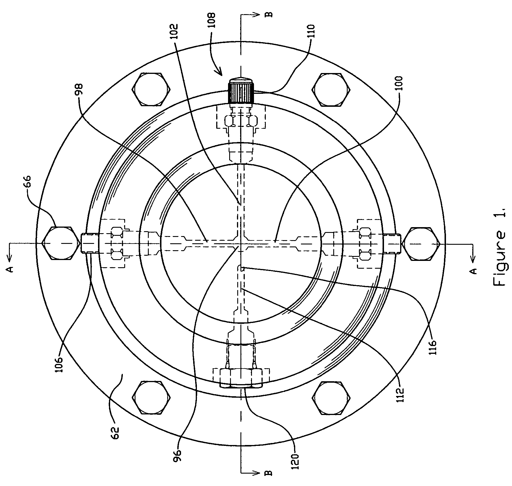
[0022]FIG. 1 is a front view of rotary union assembly housing 62 portion of the present invention. Rotary union assembly housing 62 connects to wheel end 64 using fasteners 66. Inside the rotary union assembly housing 62 extend four radial passageways 98, 100, 102, 112. As described more fully with reference to FIGS. 2–3 below, radial passageways 98, 100 supply pressurized air to tires on the rotary union assembly. Radial passageways 98, 100 comprise fittings 106. Fittings 106 are a common tire valve type that opens when a mating fitting is threaded on it and closes when the mating fitting is removed. Radial passageway 102 provides a service port 108 with fitting 110 sealably threaded to the rotary union assembly housing 62. Radial passageway 112 comprises cross drilled bore 116, and fitting 120, and functions as a vent for venting a vent chamber of the rotary union assembly.

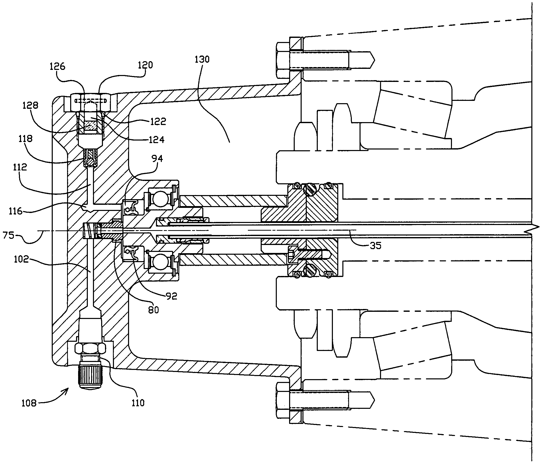
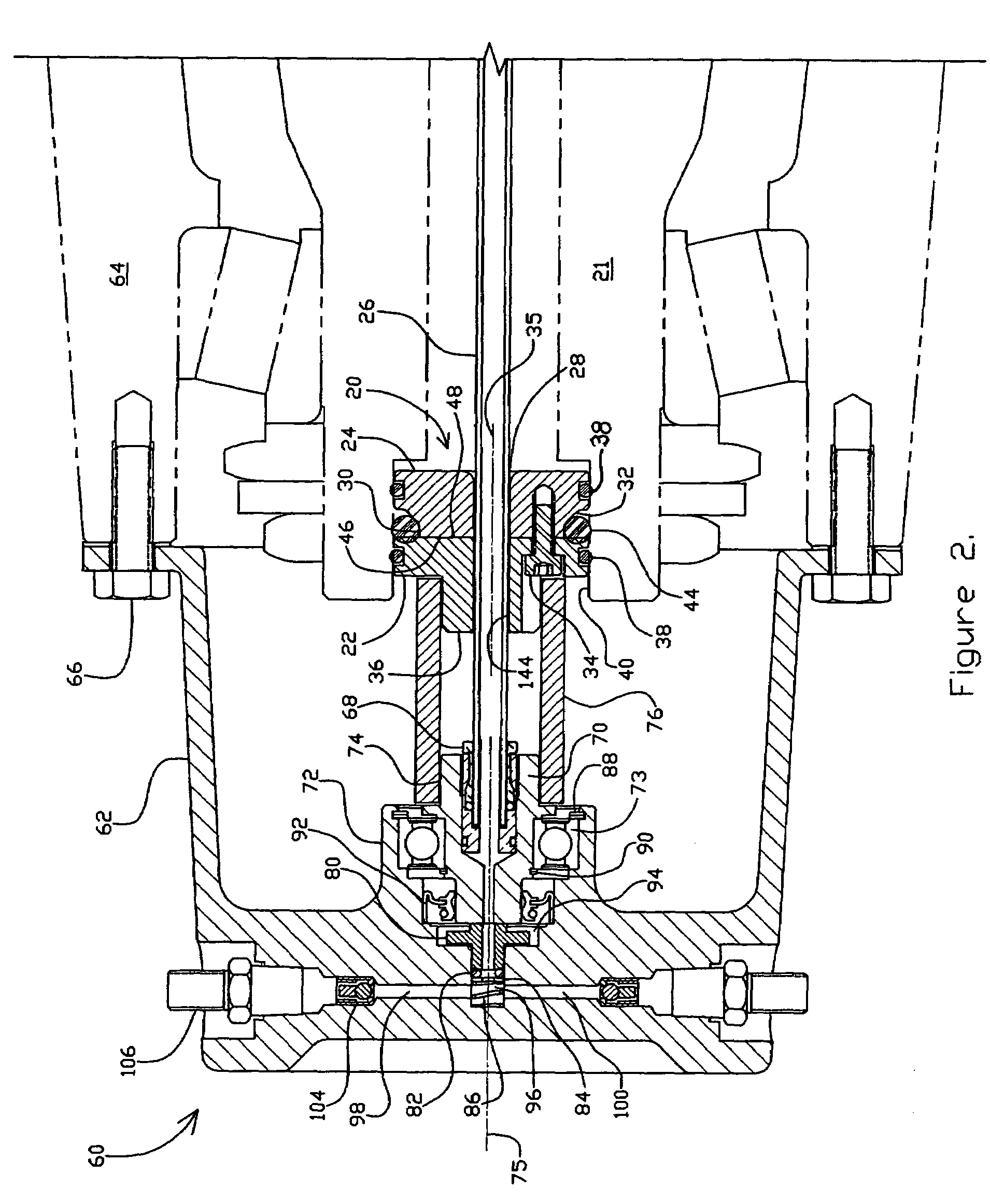
[0023]FIG. 2 is a cross-sectional view of a rotary air union taken along line A—A of FIG. 1. Shown in FIG. 2 ...


PUM


Abstract

A central tire inflation system for maintaining tire inflation on a vehicle having a torque transfer sleeve connected between an axle plug assembly and a stationary shaft on the rotary union assembly. A flexible conduit extends through the axle plug to the rotary union assembly and is used to provide air pressure to tires connected to the rotary union assembly. The torque transfer sleeve limits rotational torque on the flexible conduit. Primary and secondary seals are provided on the rotary union assembly as well. A vent chamber between the primary and secondary seals allows the release of air which exits the primary seal, which prevents pressure from entering the lubrication area of the rotary union assembly.

Description

CROSS-REFERENCE TO RELATED APPLICATION(S)[0001]This application claims priority from Provisional Patent Application No. 60 / 452,401, filed on Mar. 6, 2003, entitled “Central Tire Inflation System Rotary Air Union,” invented by Christopher A. Nelson and James P. LeClaire, the contents of which is hereby incorporated by reference.BACKGROUND OF THE INVENTION[0002]The concept of monitoring, regulating, and maintaining tire pressure on a moving vehicle is not new. Tire pressure maintenance has always been important and the transportation industry has constantly promoted this subject as a means to increase tire life and fuel economy, while reducing down time and maintenance costs due to flat tires. A tire blow out on the road can leave debris that can be hazardous to other drivers. Tire pressure maintenance can decrease the possibility of tire failures and increase safe operation for the vehicle driver and other drivers on the road.[0003]Various systems have been designed and are the subje...

Claims


Application Information

Patent Timeline
IPC IPC(8): B60C29/06B60CB60C23/00B60C23/10
CPCB60C23/003B60C23/00336B60C23/00345B60C23/00354B60C23/00363
Inventor NELSON, CHRISTOPHER A.LECLAIRE, JAMES P.
Owner PRESSURE SYST INT LLC
Why Eureka
Try Eureka