
Central tire inflation system

a tire inflation system and central technology, applied in the field of vehicles, can solve the problems of difficult tire/wheel removal when

Inactive Publication Date: 2019-10-31
GM GLOBAL TECH OPERATIONS LLC
View PDF0 Cites 3 Cited by
  • Summary
  • Abstract
  • Description
  • Claims
  • Application Information

AI Technical Summary

Benefits of technology

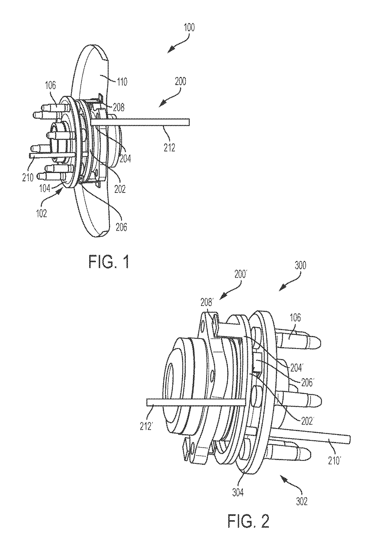
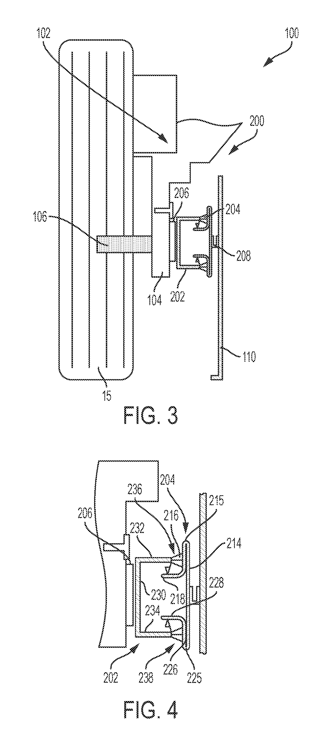
The present invention provides an air transfer ring that can transfer air between the chassis or stationary side of a vehicle and the tire / wheel or rotational components of the vehicle, regardless of the wheel design. This allows for independent control of air pressure in each individual tire / wheel, improving performance and efficiency.

Problems solved by technology

However, central tire inflation systems can make removing the tire / wheel difficult when servicing the vehicle due to the typical routing of air from the chassis or stationary side of the vehicle to the tire / wheel or rotational components and vice versa.

Method used


Image

  • Central tire inflation system
  • Central tire inflation system
  • Central tire inflation system

Examples


Embodiment Construction

[0031]Embodiments of the present disclosure are described herein. It is to be understood, however, that the disclosed embodiments are merely examples and other embodiments can take various and alternative forms. The figures are not necessarily to scale; some features could be exaggerated or minimized to show details of particular components. Therefore, specific structural and functional details disclosed herein are not to be interpreted as limiting, but merely as a representative basis for teaching one skilled in the art to variously employ the present invention. As those of ordinary skill in the art will understand, various features illustrated and described with reference to any one of the figures can be combined with features illustrated in one or more other figures to produce embodiments that are not explicitly illustrated or described. The combinations of features illustrated provide representative embodiments for typical applications. Various combinations and modifications of ...


PUM


Abstract

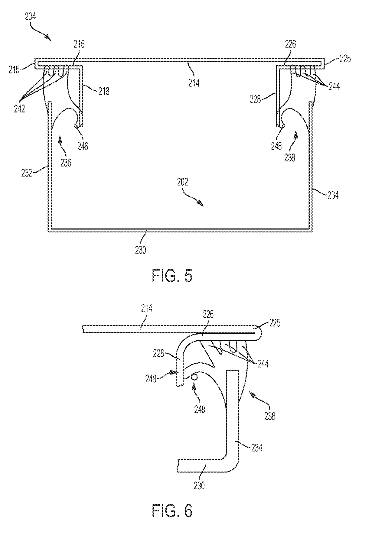
An exemplary system for controlling air pressure in a tire of a vehicle includes an air transfer ring assembly including a reservoir member, a cover member, a first air transfer member, a second air transfer member, and a sealing member configured to seal the reservoir member against the cover member and defining a pressured reserve air chamber. The reservoir member is coupled to a hub assembly of the vehicle and the cover member is coupled to a brake assembly of the vehicle to facilitate the transfer of air to and from a rotating vehicle component and a stationary vehicle component.

Description

INTRODUCTION[0001]The present invention relates generally to the field of vehicles and, more specifically, to an air transfer ring and sealing assembly for a central tire inflation system.[0002]Vehicles are often equipped with pressure-monitoring systems. A central tire inflation system uses the pressure-monitoring system to determine an optimal tire inflation pressure. However, central tire inflation systems can make removing the tire / wheel difficult when servicing the vehicle due to the typical routing of air from the chassis or stationary side of the vehicle to the tire / wheel or rotational components and vice versa.SUMMARY[0003]Embodiments according to the present disclosure provide a number of advantages. For example, embodiments of an air transfer ring according to the present disclosure enable a transfer of air to and / or from the chassis or stationary side of the vehicle to the tire / wheel or rotational components of the vehicle independent of the wheel design.[0004]In one aspe...

Claims


Application Information

Patent Timeline
IPC IPC(8): B60C23/00B60C23/04
CPCB60C23/0491B60C23/003B60C23/004B60C23/00318B60C23/00363
Inventor POULS, SCOTT R.SUTHERLIN, ROBERT G.
Owner GM GLOBAL TECH OPERATIONS LLC
Learn More