
Method and apparatus for boosting gas turbine engine performance

a gas turbine engine and performance technology, applied in the direction of gas turbine plants, machines/engines, jet propulsion plants, etc., can solve the problems of reducing the resulting power output of the engine to as little as 35% of its rated power output, and no method of incorporating these sources into gas turbine based power systems, etc., to achieve the effect of improving the performance of the pipeline system and increasing the pressure of the fluid being transmitted

Inactive Publication Date: 2013-12-31
COUSINO SR DENNIS JAMES
View PDF20 Cites 177 Cited by
  • Summary
  • Abstract
  • Description
  • Claims
  • Application Information

AI Technical Summary

Benefits of technology

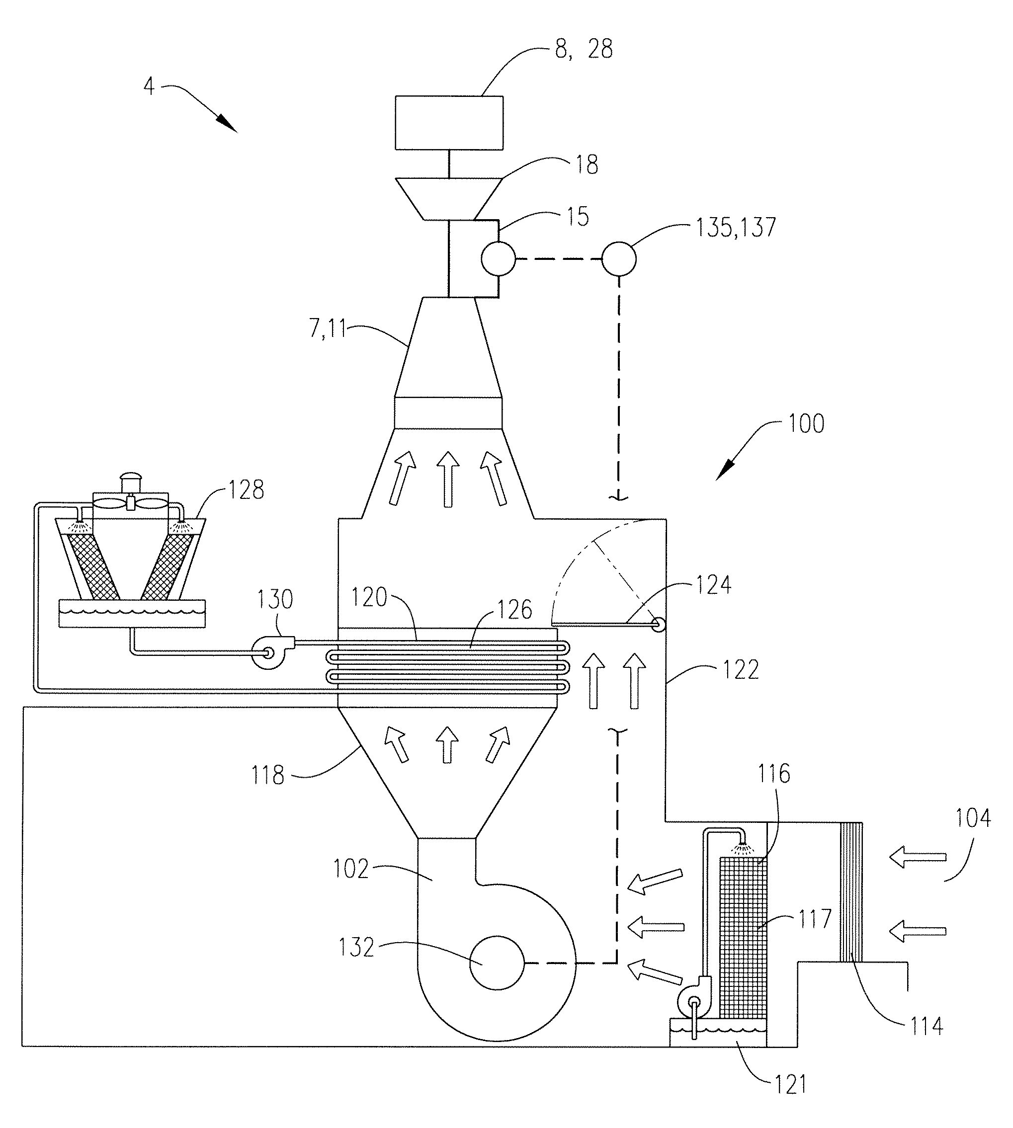
The present invention is a boosting method and apparatus for improving the performance of gas turbine engines in various applications. It increases the density of air traveling through the engine, reducing the amount of fuel required and lowering emissions. This also reduces the necessary fuel-to-air ratio and combustion temperature. Additionally, it provides consistent power output, protects the engine, reduces maintenance requirements, improves fuel efficiency, and allows older engines to meet stricter emission standards. The benefits of the invention exceed the cost and energy requirements, especially at higher elevations or during periods of higher ambient temperatures.

Problems solved by technology

Many times alternative sources of energy could be used to provide the needed shaft power, with lower overall cost, but there is currently no method of incorporating these sources into gas turbine based power systems.
Unfortunately, however, at higher ambient air temperatures and / or higher elevations, the power output of a gas turbine engine will be significantly less than the rated power output of the engine at ISO conditions (i.e., operation at sea level with an ambient air temperature of 15° C.
However, when operating, for example, at an altitude of 3,000 feet above sea level and an ambient air temperature of 100° F., the significantly lower air density encountered under these conditions will typically reduce the resulting power output of the engine to as little as 35% of its rated power output or less.
Unfortunately, in addition to other disadvantages and harmful effects, the increased engine fuel-to-air ratio increases the engine combustion temperature and thus operates to: (a) increase the levels of thermally generated nitrous oxide (NOx) and other greenhouse gas emissions discharged in the engine exhaust, (b) test the metallurgical temperature limits of the engine components, (c) accelerate and increase the need for engine maintenance and part replacement, and (d) reduce the life of the engine.
However, this approach is very costly in additional fuel and maintenance expense, and results in higher total emissions, and largely does not address directly the poor efficiency, high combustion temperature, and emissions problems experienced when operating gas turbine engines at air densities significantly lower than at the original ISO design conditions.
However, although these existing systems still have many remaining years of useful life, the ability to continue to operate these engines, without extensive internal combustion system modifications and having to pay significant emissions related penalties, is very much in question.
Unfortunately, the solutions offered heretofore by turbine engine manufacturers for improving emissions have focused on replacing existing turbine engines with new low NOx version turbine engine systems.
However, as will be apparent, the capital cost of replacing all existing industrial turbine engine systems in order to comply with current emissions requirements would be excessive.
As for prior efforts to address swings in power availability due to varying ambient temperatures, these have involved various forms of inlet air cooling, aimed at increasing density, which, unfortunately, have burdened the engine with higher parasitic operating loads and costs.
Moreover, to compensate for reduced gas turbine power at high altitude stations, the practice in the industry has simply been to use larger gas turbines with the associated higher capital and operating costs.

Method used


Image

  • Method and apparatus for boosting gas turbine engine performance
  • Method and apparatus for boosting gas turbine engine performance
  • Method and apparatus for boosting gas turbine engine performance

Examples


example

[0059]A Solar Saturn 20 gas turbine compressor drive engine having a rated shaft power output of 1.4 MW at ISO conditions is operated at a site wherein the site elevation is 2900 feet above sea level, the ambient air temperature is 120° F., and the ambient relative humidity is 0.1. The Solar Saturn 20 engine is first operated with direct intake of filtered air from the atmosphere and is used to drive a natural gas compressor. At these atmospheric air conditions and an altitude of 2900 feet, the engine will operate at an efficiency of 0.2032 and provide an engine shaft power output of 0.9423 MW. The net power provided to the gas compressor which is driven by the Solar Saturn 20 engine will be 0.731 MW.

[0060]In accordance with the present invention, under these same atmospheric and elevational conditions, an inventive boost system 100 using an electrically driven centrifugal boosting fan 102, a pre-boosting evaporative cooler and humidifier 116, and a post-boosting water coolant syste...


PUM


Abstract

A method and apparatus for boosting the performance of gas turbine engines, pipelines, and other applications using gas turbine engine systems. A pressurizing device or other source is preferably used to deliver an intake air stream to the gas turbine engine at at least 2% above atmospheric pressure. The pressurizing device of other source is preferably not mechanically driven by the gas turbine engine itself.

Description

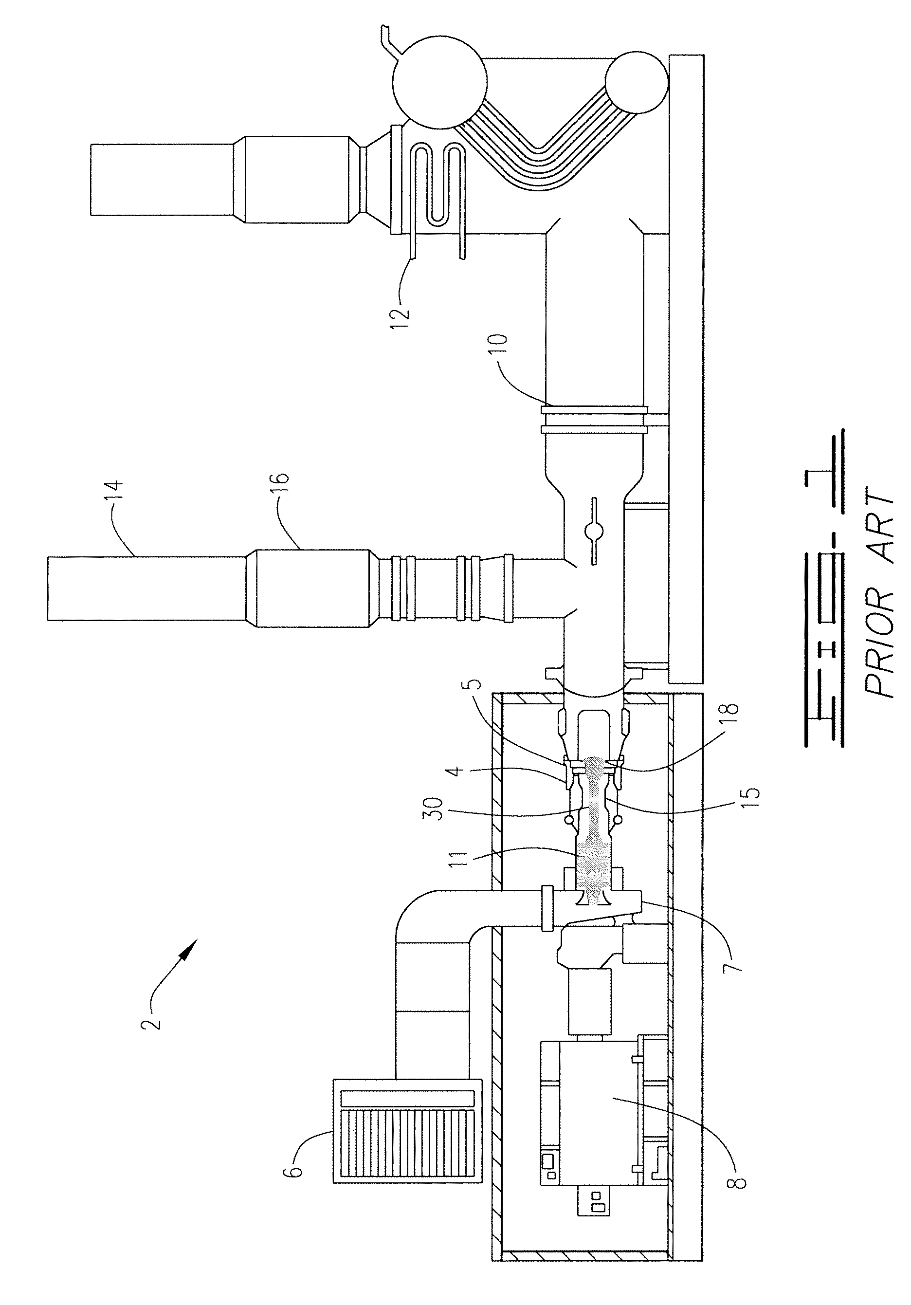
FIELD OF THE INVENTION[0001]The present invention relates to apparatuses and methods for improving emissions and enhancing the performance of gas turbine engines and to gas turbine engine systems which use and are produced by such apparatuses and methods.BACKGROUND OF THE INVENTION[0002]Gas turbine engines are commonly used for numerous different purposes and applications. Unless stated otherwise, the term “gas turbine engine” is used herein and in the claims to refer generally to the well known type of internal combustion rotary engine which comprises: an air intake; an air intake compressor; a combustor; a power turbine; and an exhaust. All of these components are typically contained within a single engine housing. The engine compressor typically employs a series of rotating and stationary compressor blades to compact and pressurize the intake air. In the combustor, fuel is added to the pressurized air and ignited whereby the hot combustion gas formed in the combustor then expands...

Claims


Application Information

Patent Timeline
IPC IPC(8): F02C1/00
CPCF02C1/00F02C1/002
Inventor COUSINO, SR., DENNIS, JAMES
Owner COUSINO SR DENNIS JAMES
Learn More