Meat grinder with suction base

a meat grinder and suction base technology, applied in the field of new meat grinders, can solve the problems of small meat particles, inconvenient grinding process, and most people's inability to mount the grinder on the kitchen tabl

Active Publication Date: 2007-04-24
WONG
View PDF10 Cites 50 Cited by
  • Summary
  • Abstract
  • Description
  • Claims
  • Application Information

AI Technical Summary

Benefits of technology

[0004]Based on the above issues, the purpose of this invention is to provide a meat grinder with a suction base and manual operated grinding unit. Turning a rotating disk first, the user will firmly fix this meat grinder to the kitchen table surface, as well as lock the base to the upper grinding part. Then the user can rotate the handle to spin the screw bolt and the pedal blade, pushing meat to go through the pedal blade, and be grinded into ground meat, thus finishing the grinding process. Meanwhile, this grinder is made up by the grinding unit and the suction base. The grinding unit and the suction base can be separated at cleansing time, making it easier to clean. Thus it resolves the two issues mentioned above.
[0010]Meanwhile, the above mentioned suction disk is connected to the grinding unit through a suction disk locking device between them. The device includes a suction disk stick spring that will be installed on the top of suction disk stick. This spring has a shape of letter C to lock the protruding suction disk stick axle and prevent it from slipping out.
[0011]Prior to grinding, the user only needs to rotate the rotating disk. That will not only mount the meat grinder to the kitchen table, but also lock the base with the upper grinding unit. Then the user can repetitively rotate the handle to spin the screw bolt and the pedal blade, pushing meat to go through the pedal blade, and be grinded into ground meat, thus finishes the grinding process. That resolved the troubles that caused by the fact that current meat grinders cannot be mounted to kitchen tables during grinding operation. Meanwhile, this grinder consists of two assembled units: the grinding unit and the suction base. The grinding unit and the suction base can be separated at cleansing time, making it easier to clean. Thus, it resolved the two issues mentioned above.

Problems solved by technology

This forces the meat to pass the rotating pedal blade under pressure, thus smashed into meat particles of small size.
Currently, most manual grinders use the same method to grind meat, but most of them cannot mount the grinder onto the kitchen table.
Thus the grinding process is not very convenient.
This makes them difficult to clean.

Method used


Image

  • Meat grinder with suction base
  • Meat grinder with suction base
  • Meat grinder with suction base

Examples


Embodiment Construction

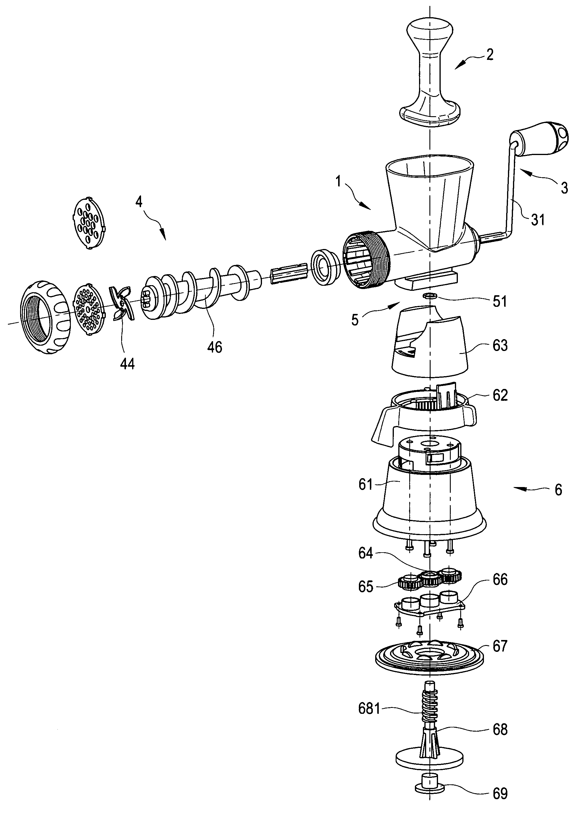
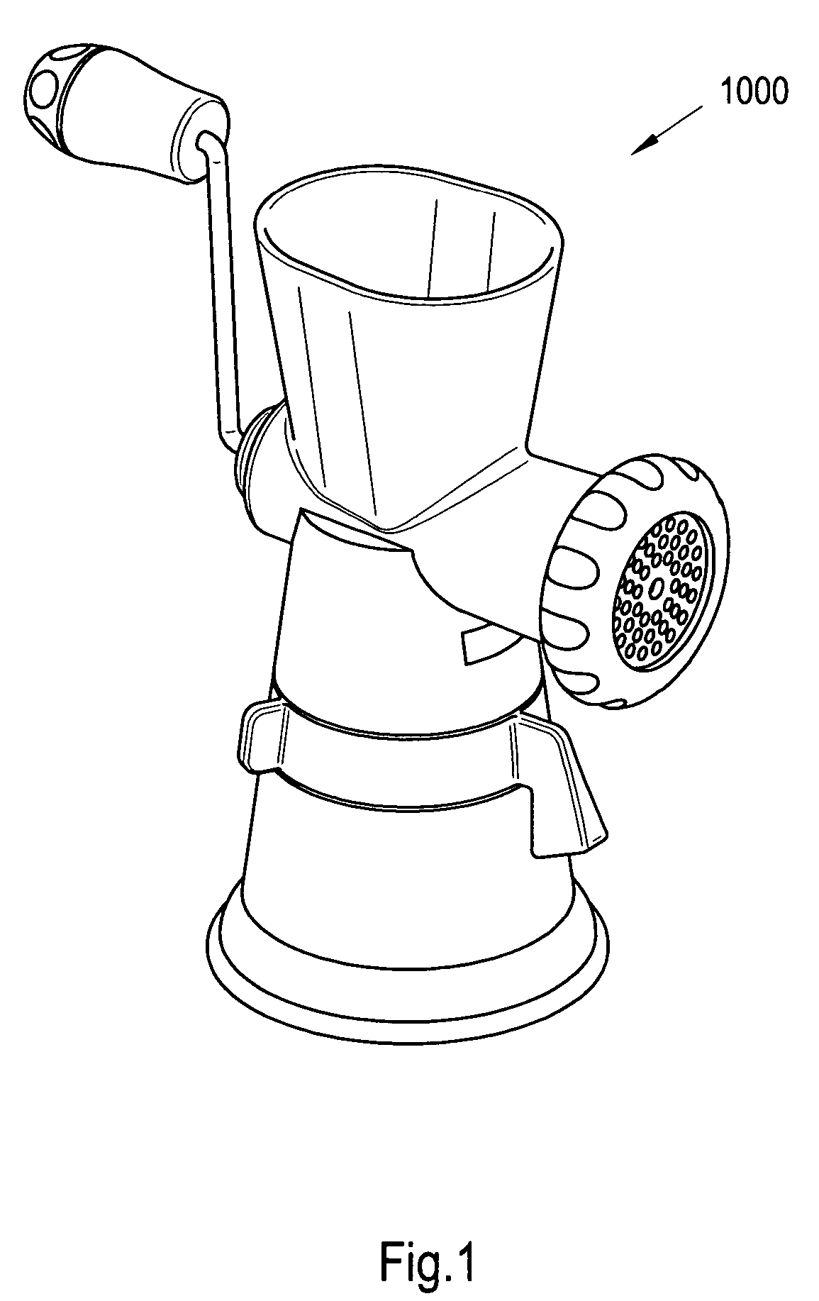
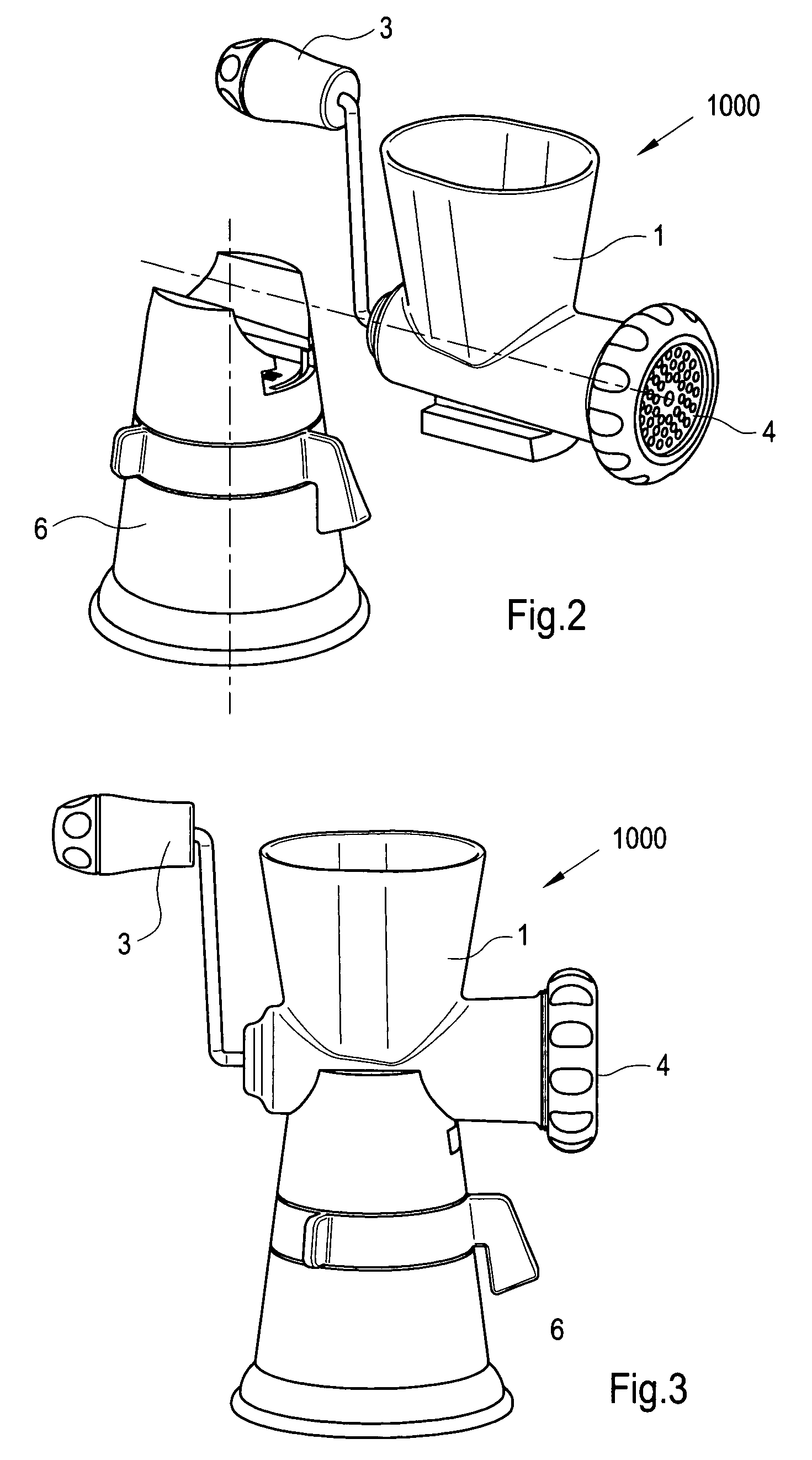
[0028]FIG. 1 shows the front view of this invention: The meat grinder with a suction base 1000. FIG. 2 and FIG. 3 show the dissembled view and side view of this invention: The meat grinder with a suction base, respectively. It consists of: a grinding unit 1 that will be placed on the upper portion of this invention, a pressing bar 2 that will be placed into the grinding unit 1, a handle 3 that will be placed on the side of the grinding unit 1, a bolt / pedal blade unit 4 that will be placed inside the grinding unit 1, which, once connected with handle 3 inside the grinding unit 1, will achieve the goal of grinding meat, a fixing suction unit 6 that will be placed on the lower portion of this invention, and a suction disk locking unit 5 that will be placed between fixing suction unit 6 and grinding unit 1.

[0029]Referring to FIG. 4, the dissembled internal view of the meat grinder with a suction base is shown. The Figure shows the position of the abovementioned six units and their compo...


PUM


Abstract

This invention contains a suction base meat grinder consisting of a meat grinder with a suction base and manually operated grinding unit. Turning a rotating disk first, the user will firmly fix this meat grinder to the kitchen table surface, as well as lock the base to the upper grinding part. Then the user can rotate the handle to spin the screw bolt and the pedal blade, pushing meat to go through the pedal blade, and be grinded into ground meat, thus finishing the grinding process. Meanwhile, this grinder is made up by the grinding unit and the sucking base. The grinding unit and the sucking base can be separated at cleansing time, making it easier to clean.

Description

TECHNICAL FIELD[0001]This invention is about a new meat grinder, in particular, a meat grinder with a suction base and manual operated grinding unit.BACKGROUND TECHNOLOGY[0002]Meat grinder is a tool used to grind large chunks of meat into ground meat. This invention achieves this goal manually by repetitively rotating the handle to drive the screw bolt and pedal blade into rotation. This forces the meat to pass the rotating pedal blade under pressure, thus smashed into meat particles of small size. The characteristic of this invention is its fixing sucking disk at the bottom. Before grinding, by turning the rotating disk, the user can fix the meat grinder on the kitchen table, and lock the base with its grinding unit. Currently, most manual grinders use the same method to grind meat, but most of them cannot mount the grinder onto the kitchen table. Thus the grinding process is not very convenient.[0003]Besides, most modern grinders are all-in-one, i.e., the grinding unit is fixed to...

Claims


Application Information

Patent Timeline
Patent Type & Authority Patents(United States)
IPC IPC(8): B02C17/16A47G1/17
CPCB02C18/305
Inventor WONG, YAN KWONG
Owner WONG
Why Eureka
Try Eureka