Portable support for laptop computer

a laptop computer and support technology, applied in the direction of machine supports, furniture parts, dismountable cabinets, etc., can solve the problems of low sperm count, easy to find a working surface, and elevation of temperature in the scrotal area

Inactive Publication Date: 2007-04-24
THOMAS GEORGE R
View PDF36 Cites 43 Cited by
  • Summary
  • Abstract
  • Description
  • Claims
  • Application Information

AI Technical Summary

Benefits of technology

[0007]There is provided a support for supporting a laptop computer comprising a top tray in cooperation with but not attached to a bottom tray, the top tray moveable from an inclined working position to a flat storage position, the top tray comprising a top base having a first end and a second end opposite the first end, and having a first lip proximal the first end, the bottom tray comprising a bottom base having a first end and a second end opposite the first end, and having a flange extending upwardly proximal the first end, the flange and / or the bottom base having an aperture for accepting the first lip of the top tray, the first lip of the top tray engaging the bottom base through the aperture when the top tray is in the storage position to limit sliding of the top tray toward the second end of the bottom base when the top tray is in the storage position, and the support comprising means for preventing the top tray from sliding towards the second end of the bottom base when the top tray is in the working position.
[0008]The top and bottom trays of the support are designed to cooperate to provide an inclined working position in which the support can rest on the lap of a sitting or reclining person. This provides a level surface on which to set a laptop computer while protecting the person from the heat generated by the computer. The trays are also designed to cooperate to provide a flat storage position in which the laptop computer together with the support can be conveniently inserted into the laptop computer's carrying case. Switching from the working position to the storage position and vice versa may be easily accomplished by completely separating the top tray from the bottom tray and moving the top tray from one position to the other while the laptop computer remains on the top tray. The top tray and the bottom tray are separate pieces that cooperate together but are not attached to each other by hinges, flexible material or the like.
[0009]The top and bottom trays may further comprise a variety of features that cooperate to enhance the convenience, safety and versatility of the support.

Problems solved by technology

Although some places have tables, desks and the like to set the computer on when working, in many places, such as airports, a ready working surface is not easily found.
The former results in an elevation of temperature in the scrotal area, contributing to lower sperm count in men, and the latter in a stiff thoracic spine contributing to back ache.
Further, radiation (e.g. heat and electric and magnetic fields) generated by laptop computers can be uncomfortable and hazardous to health.
Prior art supports fall short on one or more of these requirements.
However, prior art support devices of this nature either cannot be adjusted to lose the wedge-shape or rely on some kind of hinge system to collapse down.
In the latter, the hinge system is complicated to use or is prone to breaking thereby detracting from the convenience or utility of the support.
Such an arrangement requires that either one of the support panels be smaller than the other thereby providing less working supporting surface, or the presence of a fourth hinged panel which results in a thicker profile making it more difficult to store the support in the laptop carrying case.
In addition, the “living hinges” limit the construction material to plastic, therefore embodiments that also protect against radiation cannot be made easily.
In addition, “living hinges” are prone to breaking with time and use, which would destroy the usefulness of the support.

Method used


Image

  • Portable support for laptop computer
  • Portable support for laptop computer
  • Portable support for laptop computer

Examples


Embodiment Construction

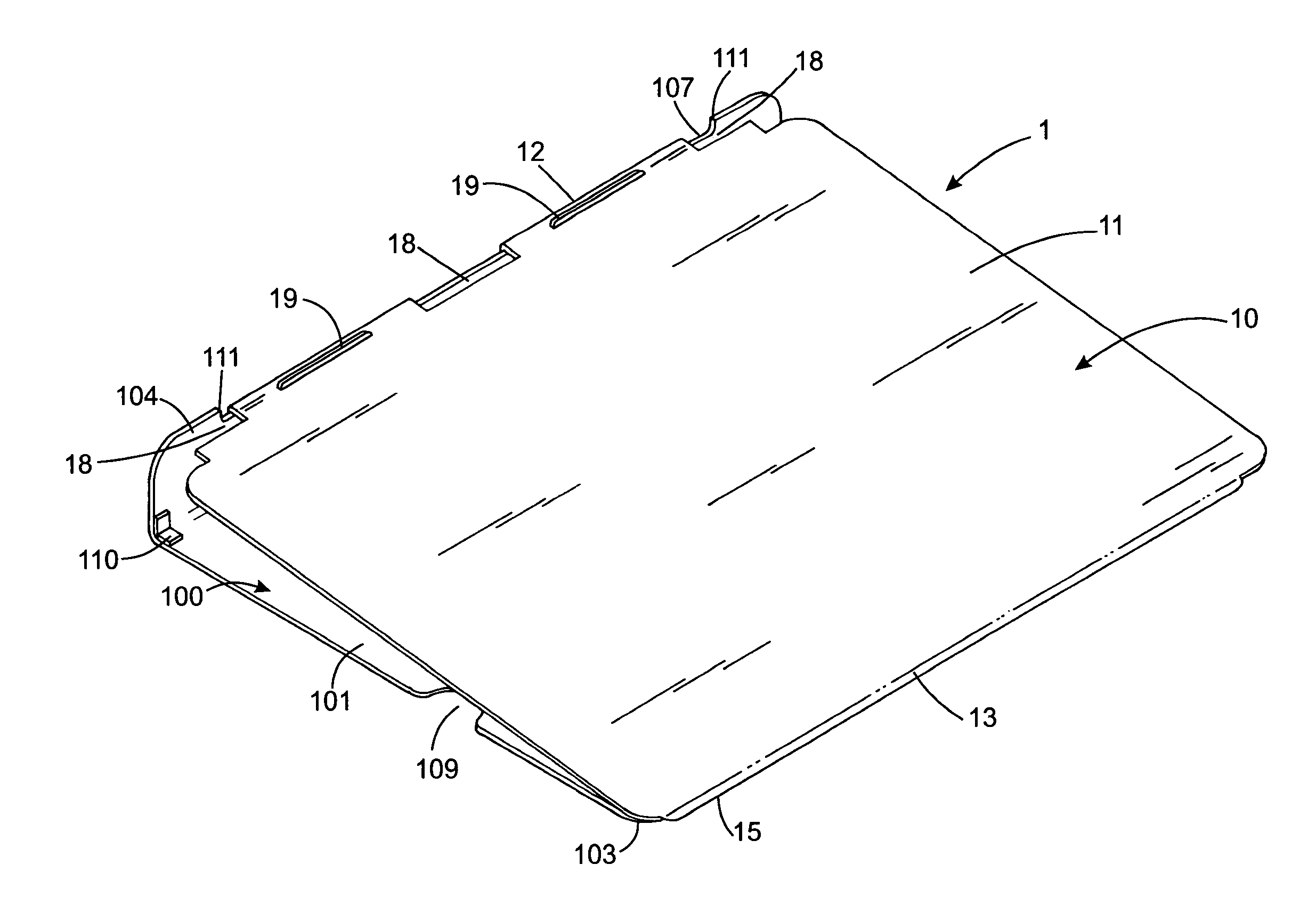
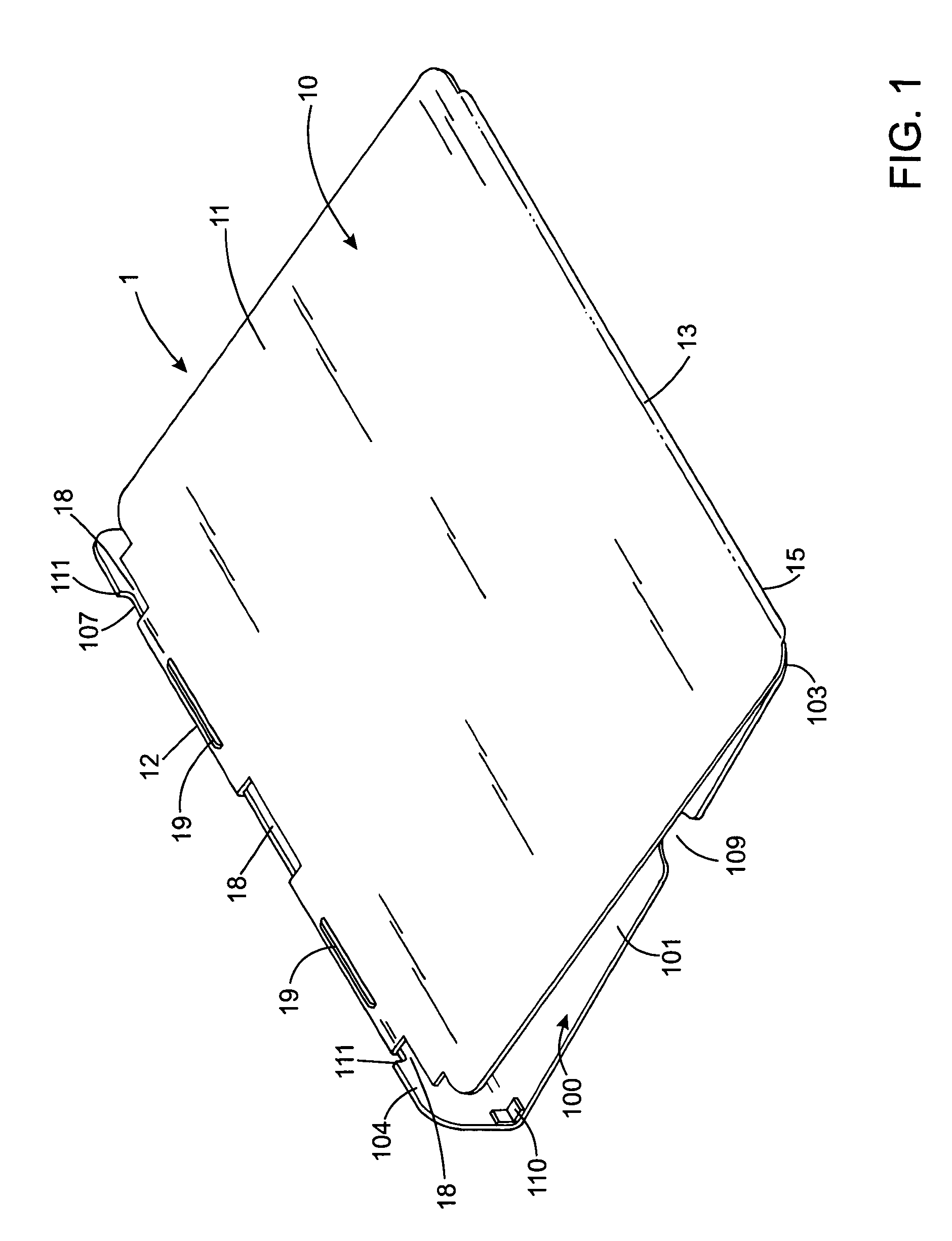
[0061]Referring to FIGS. 1–9, a support of the present invention generally depicted at 1 comprises a top tray 10 and a bottom tray 100. Top tray 10 and bottom tray 100 cooperate to form support 1 without the need for the trays to be attached. Support 1 has a working position depicted in FIGS. 1–2 and a storage position depicted in FIGS. 3–5.

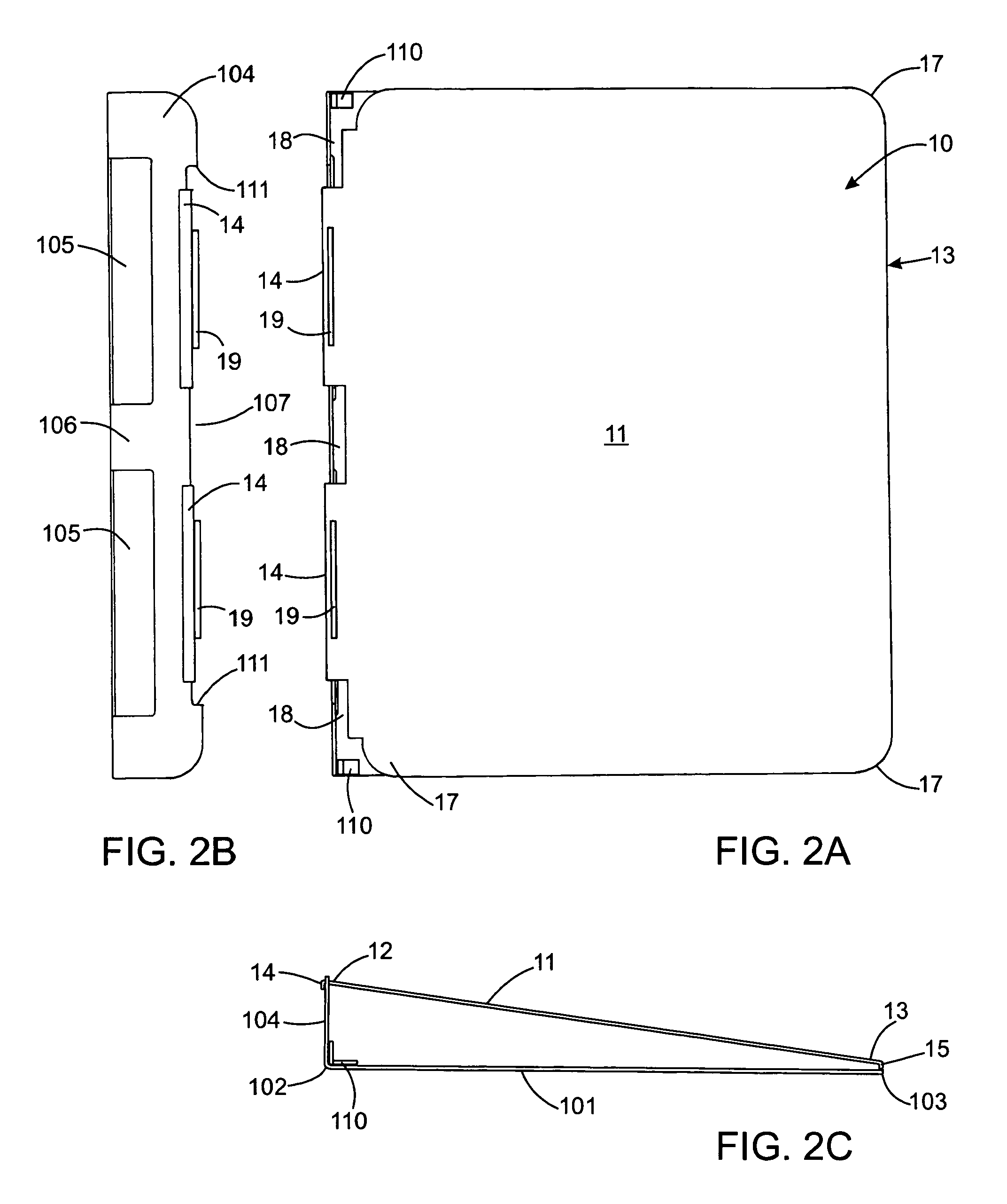
[0062]Referring specifically to FIGS. 6 and 7, top tray 10 is made of a single piece of anodized aluminum 1 mm thick and comprises a top base 11 that is 31.8 cm wide and 26.0 cm deep. Top base 11 has a rear end 12 and a front end 13. At rear end 12 there are two downwardly depending spaced-apart rear lips 14. At front end 13 is a downwardly depending front lip 15. Between and beside spaced-apart rear lips 14, the top base 11 is notched out at rear end 12. Ridges 19 proximal rear end 12 are about 3 mm thick and 5 mm high. Corners 16 of rear end 12 are cut-out and rounded. Corners 17 of front end 13 are also rounded. Lips 14,15 are each about 1 mm ...


PUM


Abstract

A support for supporting a laptop computer has a top tray in cooperation with but not attached to a bottom tray. The top tray is moveable from an inclined working position to a flat storage position. The top tray has a top base having a lip proximal one end. The bottom tray has a bottom base having a flange extending upwardly proximal one end. The flange and / or the bottom base of the bottom tray has an aperture for accepting the lip of the top tray. The lip of the top tray may engage the top of the flange when the top tray is in the working position to prevent the top tray from sliding towards the opposite end of the bottom tray. The lip of the top tray engages the bottom base through the aperture when the top tray is in the storage position to limit sliding of the top tray toward the opposite end of the bottom tray. In the storage position, the support is readily packed together with the computer in the computer's carrying case. In the working position, the support provides good protection from heat generated by the computer, provides cooling for the computer, improves a user's sitting posture and reduces eye strain.

Description

FIELD OF THE INVENTION [0001]The present invention is directed to a portable support and radiation shield for a laptop computer.BACKGROUND OF THE INVENTION [0002]Portable laptop computers permit people to do work out of the normal office environment. Laptop computers are typically stored and transported in a carrying case. Although some places have tables, desks and the like to set the computer on when working, in many places, such as airports, a ready working surface is not easily found. Therefore, many people use their laps to support the laptop computer while working from a seated position. In balancing the laptop computer with its keyboard on the lap, a person tends to keep the thighs closed and the shoulders stooped forward. The former results in an elevation of temperature in the scrotal area, contributing to lower sperm count in men, and the latter in a stiff thoracic spine contributing to back ache. Further, radiation (e.g. heat and electric and magnetic fields) generated by...

Claims


Application Information

Patent Timeline
Patent Type & Authority Patents(United States)
IPC IPC(8): A47B95/00A47G29/00B65D19/00
CPCA47B23/043F16M13/00Y10S248/918Y10S248/919Y10S248/917F16M11/22F16M11/38F16M13/04
Inventor THOMAS, GEORGE R.
Owner THOMAS GEORGE R
Why Eureka
Try Eureka