Image forming apparatus

Inactive Publication Date: 2007-04-24
RISO KAGAKU CORP
View PDF16 Cites 3 Cited by
  • Summary
  • Abstract
  • Description
  • Claims
  • Application Information

AI Technical Summary

Benefits of technology

[0008]It is an object of the present invention to provide an image forming apparatus capable of eliminating density unevenness in the head overlapped regions only by rough head alignment.

Problems solved by technology

Unfortunately, the conventional techniques including Jpn. Pat. Appln. KOKAI Publication No. 5-57965 described above have the problem that highly accurate head alignment is necessary.

Method used


Image

  • Image forming apparatus
  • Image forming apparatus
  • Image forming apparatus

Examples


Embodiment Construction

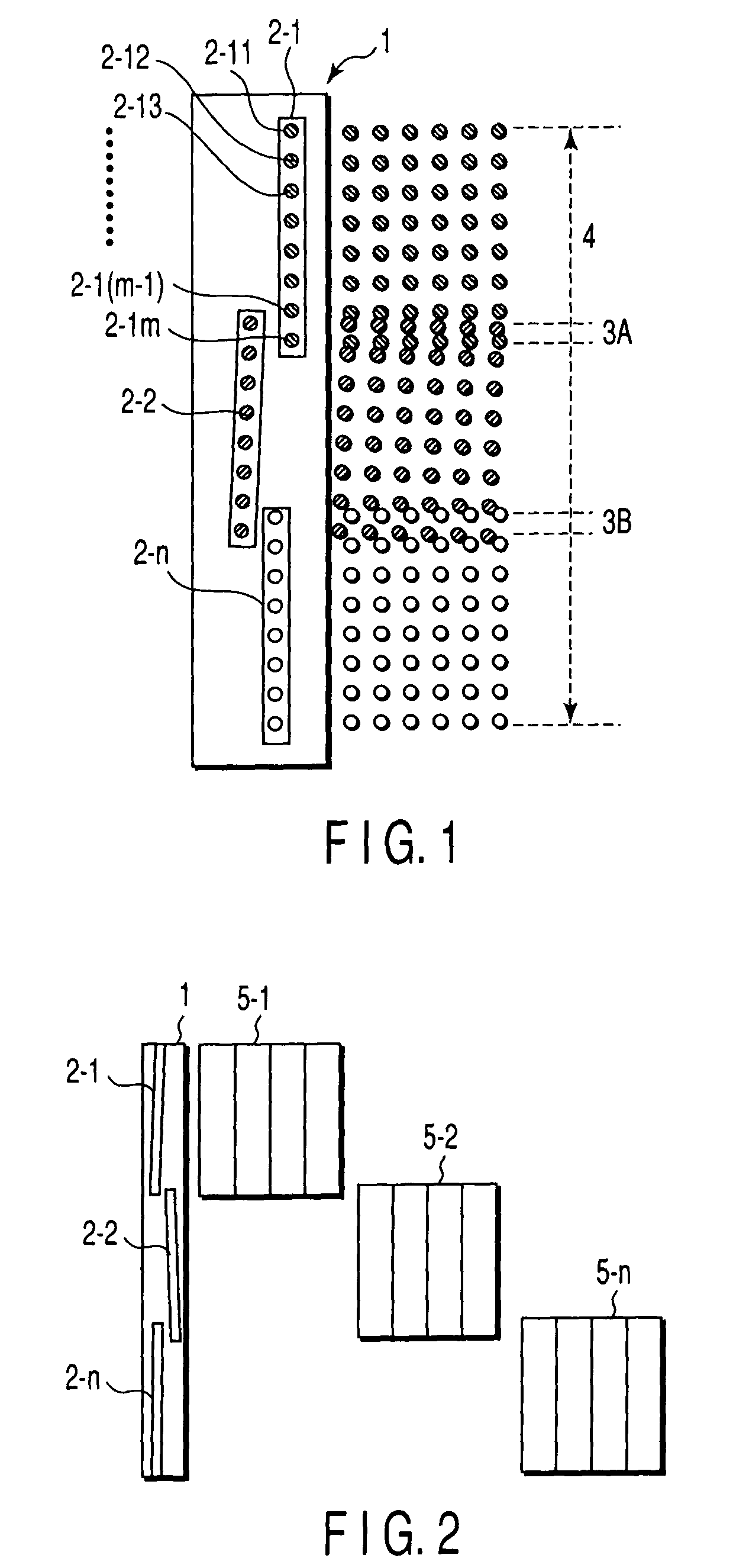
[0018]An embodiment of the present invention will be described in detail below with reference to the accompanying drawing. FIG. 1 is a view showing an outline of a recording head unit including a plurality of recording heads of an inkjet printer to which the present invention is applied. As shown in FIG. 1, a plurality of recording heads 2-1, 2-2, . . . , 2-n are arranged on a base 1 in substantially the same direction as the arranging direction of nozzles (recording elements; 2-11, 2-12, . . . , 2-1(m−1), and 2-1m for the recording head 2-1) for discharging printing ink so as to have predetermined overlapped regions 3A and 3B between the heads, thereby forming one recording head unit. Reference numeral 4 denotes a recording width. A recording head unit having this arrangement records one page on a recording medium by performing scan at least once.

[0019]FIG. 2 is a view for explaining printing of test charts used in this embodiment. In this embodiment, test charts 5-1, 5-2, and 5-n ...


PUM


Abstract

An image forming apparatus includes a recording head unit in which a plurality of recording heads are arranged in substantially the same direction as the arranging direction of recording elements such that an overlapped region is formed between the heads, a set angle / overlapped region detector which detects the width of the overlapped region of each of the plurality of recording heads from a predetermined test chart printed using the recording head unit, and an image data distributor which distributes image data input to each of the plurality of recording heads, in accordance with the detected width of the overlapped region between the heads. This apparatus achieves an effect of eliminating density unevenness in the head overlapped region only by rough head alignment.

Description

CROSS-REFERENCE TO RELATED APPLICATIONS[0001]This is a Continuation Application of PCT Application No. PCT / JP02 / 00890, filed Feb. 4, 2002, which was not published under PCT Article 21 (2) in English.[0002]This application is based upon and claims the benefit of priority from the prior Japanese Patent Application No. 2001-029835, filed Feb. 6, 2001, the entire contents of which are incorporated herein by reference.BACKGROUND OF THE INVENTION[0003]1. Field of the Invention[0004]The present invention relates to an image forming apparatus.[0005]2. Description of the Related Art[0006]A high-speed image forming apparatus capable of simultaneously forming images of a plurality of lines by one-time scan by arranging a plurality of recording heads in substantially the same direction as a nozzle arranging direction such that overlapped regions are formed between the heads is conventionally known. In addition, various methods of improving image forming apparatuses of this type have been propos...

Claims


Application Information

Patent Timeline
IPC IPC(8): B41J29/393B41J2/145B41J2/155B41J2/21B41J2/51
CPCB41J2/145B41J2/155B41J2/2135B41J29/393B41J2202/20B41J29/00
Inventor IOKA, KENKOMIYA, YASUHIRO
Owner RISO KAGAKU CORP
Why Eureka
Try Eureka