Thermal head

A technology of thermal head and heating element, applied in the field of thermal head, can solve problems such as heat release deviation, resistance value deviation, uneven printing density, etc., achieve uniform heating, eliminate uneven density, and good printing results

Inactive Publication Date: 2014-03-12
ALPS ALPINE CO LTD
View PDF8 Cites 0 Cited by
  • Summary
  • Abstract
  • Description
  • Claims
  • Application Information

AI Technical Summary

Problems solved by technology

[0009] However, the main cause of the influence on the heat generation of the heating element 6 and the unevenness of the printed density is not limited to the deviation of the resistance value of the individual electrode 9, but the heat dissipation due to the difference in the capacity (volume) of the individual electrode 9. Deviation is also one of the main reasons

Method used


Image

  • Thermal head
  • Thermal head
  • Thermal head

Examples


Embodiment Construction

[0027] Hereinafter, the wiring pattern of the individual electrodes of the thermal head in the embodiment of the present invention will be described. In addition, unless otherwise specified, the thermal head of the present invention has the same structure as the conventional structure described above.

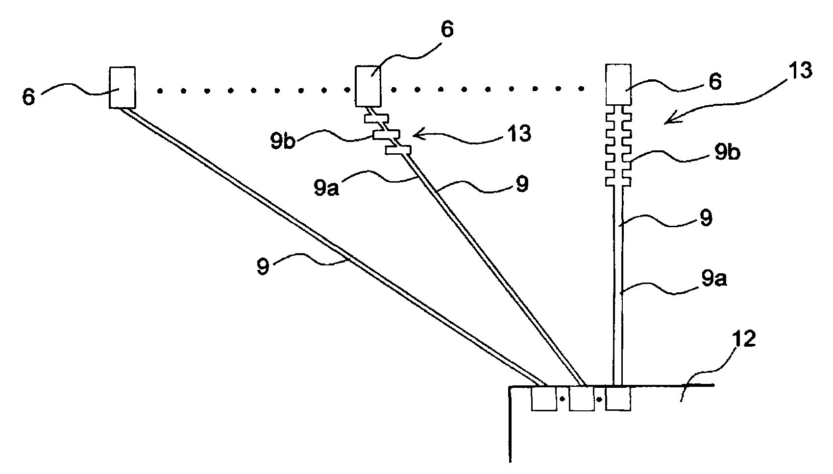
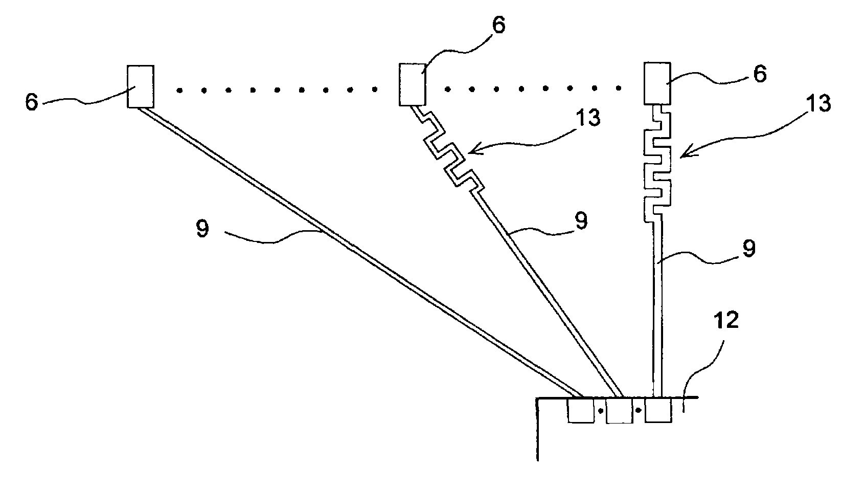
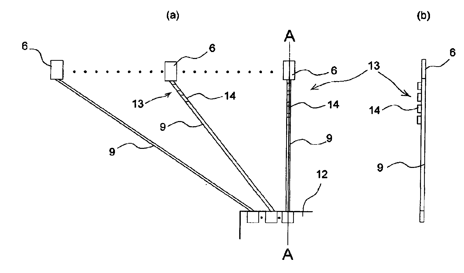
[0028] In the present embodiment, in the wiring pattern electrically connecting each heating element 6 and the individual electrodes 9 of the driver IC 12, there is formed a circuit for making the difference in capacity (volume) of the conductors of the individual electrodes 9 (hereinafter simply referred to as "capacity"). The capacity adjustment section 13 is adjusted so that the difference ") becomes smaller, and the wiring pattern of the above-mentioned individual electrodes 9 is formed so that the wiring resistance thereof is adjusted to be constant.

[0029] Specifically, as figure 1 As shown, in the main line 9a of the wiring pattern of the individual electrode 9 that ...


PUM


Abstract

A thermal head includes an insulating head substrate, one or a plurality of driver ICs, a plurality of heat generating elements that is arranged on the head substrate in a main scanning direction, a plurality of individual electrodes that is provided on the head substrate at one ends of the respective heat generating elements and connects the respective heat generating elements to the driver ICs, and a common electrode that is provided on the head substrate at the other ends of the respective heat generating elements so as to be common to the heat generating elements. Capacitance adjustment portions, which adjust capacitance difference between the respective individual electrodes so that the capacitance difference is reduced, are formed at a wiring pattern of the individual electrodes.

Description

technical field [0001] The present invention relates to a thermal head used in a printing section of a printer. Background technique [0002] The thermal head 1 mounted in the printing section of the printer, such as Figure 7 As shown, the head substrate 2 is included. On the head substrate 2, the heat storage layer 3a is formed of a heat insulating material such as glass. A part of the thermal storage layer 3a is provided with a cylindrical partial glaze 3b. On the heat storage layer 3, a heating resistor layer 4 is laminated with a predetermined width along the main scanning direction, and a heating element 6 is formed by the heating resistor layer 4 and an electrode E formed by forming the heating resistor layer 4. Constructed of electrified aluminum (Al). In addition, a protective layer 11 is formed, wherein the protective layer 11 is made of SiAlON or Ta 2 o 5 and other wear-resistant materials, and cover the heating resistor layer 4 and the electrode layer E cons...

Claims


Application Information

Patent Timeline
Patent Type & Authority Patents(China)
IPC IPC(8): B41J2/335B41J2/345
CPCB41J2/35B41J2/345
Inventor 荒内进
Owner ALPS ALPINE CO LTD
Why Eureka
Try Eureka