LED lighting with adjustable light projecting direction

a technology of led lighting and projecting direction, which is applied in the direction of lighting and heating apparatus, lighting support devices, lighting applications, etc., can solve the problems of large amount of heat, insufficient space for mounting conventional light sources, and inconvenient use of conventional light sources, etc., to achieve convenient and convenient mounting and disassembly.

Inactive Publication Date: 2007-04-24
LIN CHU HSIEN
View PDF1 Cites 136 Cited by
  • Summary
  • Abstract
  • Description
  • Claims
  • Application Information

AI Technical Summary

Benefits of technology

[0011]In the LED lighting with adjustable light projecting direction according to the present invention, the metal cylindrical members located at two ends of the lamp bank are electrically connected to positive and negative electrodes of a power supply, and the two metal end plates serve as two power input ends of the lamp bank. Therefore, when the lamp bank is rotated about the two metal cylindrical members, the two metal end plates keep in contact with and accordingly electrically connected to the metal cylindrical members to keep

Problems solved by technology

However, there are also many relatively small storing and/or displaying spaces, such as book cases, book shelves, shoe cabinets, wardrobes, showcases and show windows in bakeries and jeweler's shops, etc., that require sufficient light sources to highlight the displayed products but do not have enough space to mount the conventional light sources.
In other words, the conventional light sources are not suitable or practical for use in the narrower spaces due to their big volume.
However, they usually have a big volume and

Method used


Image

  • LED lighting with adjustable light projecting direction
  • LED lighting with adjustable light projecting direction
  • LED lighting with adjustable light projecting direction

Examples


Embodiment Construction

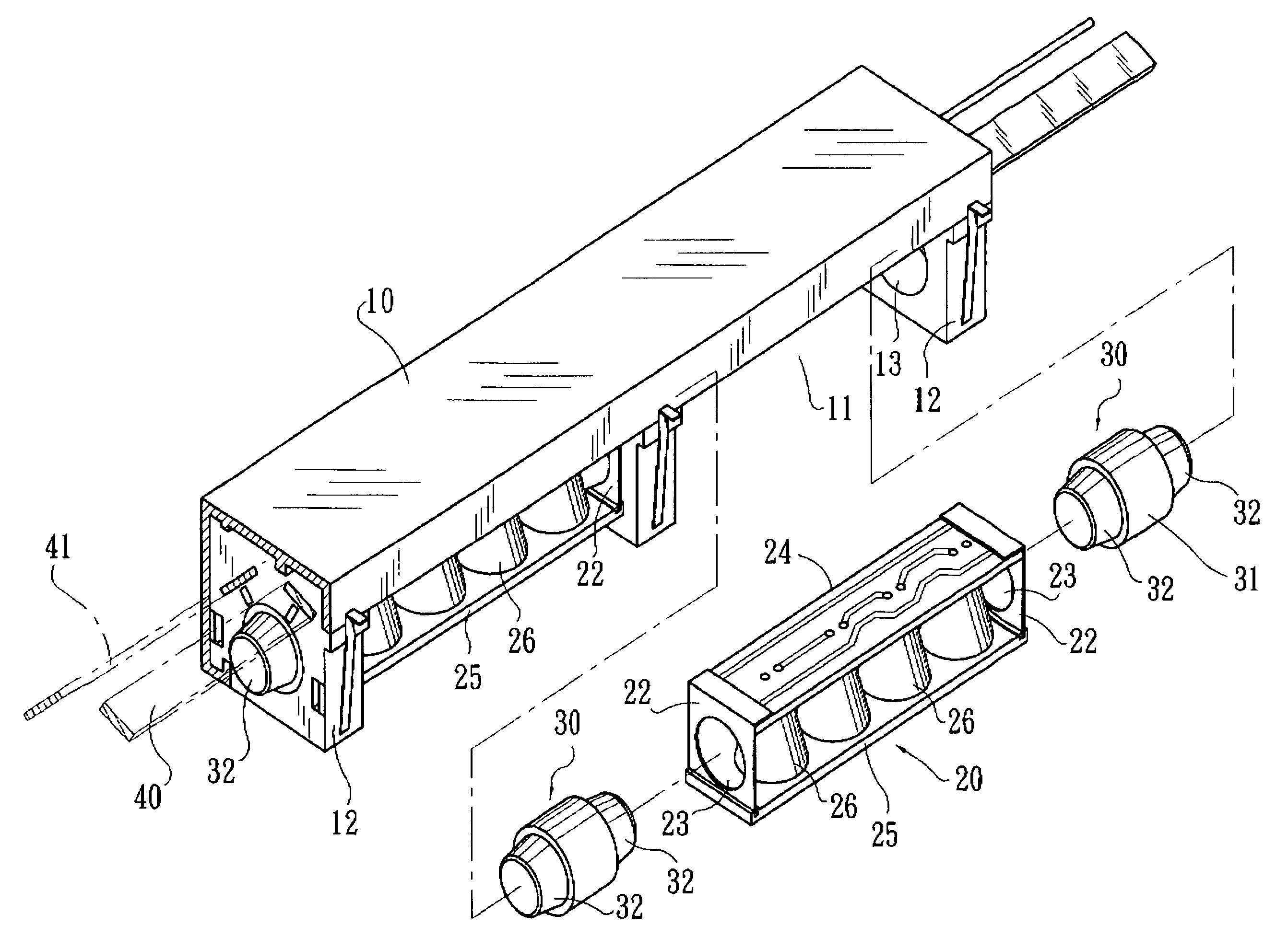
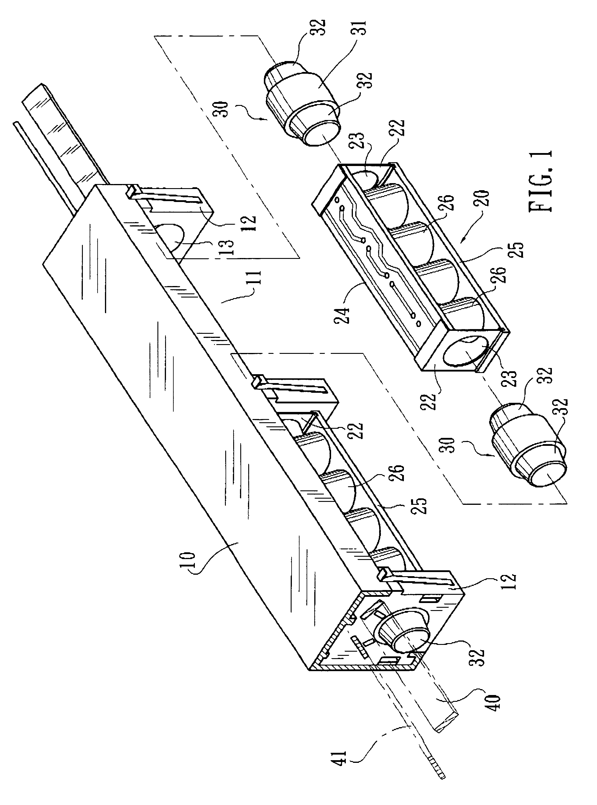
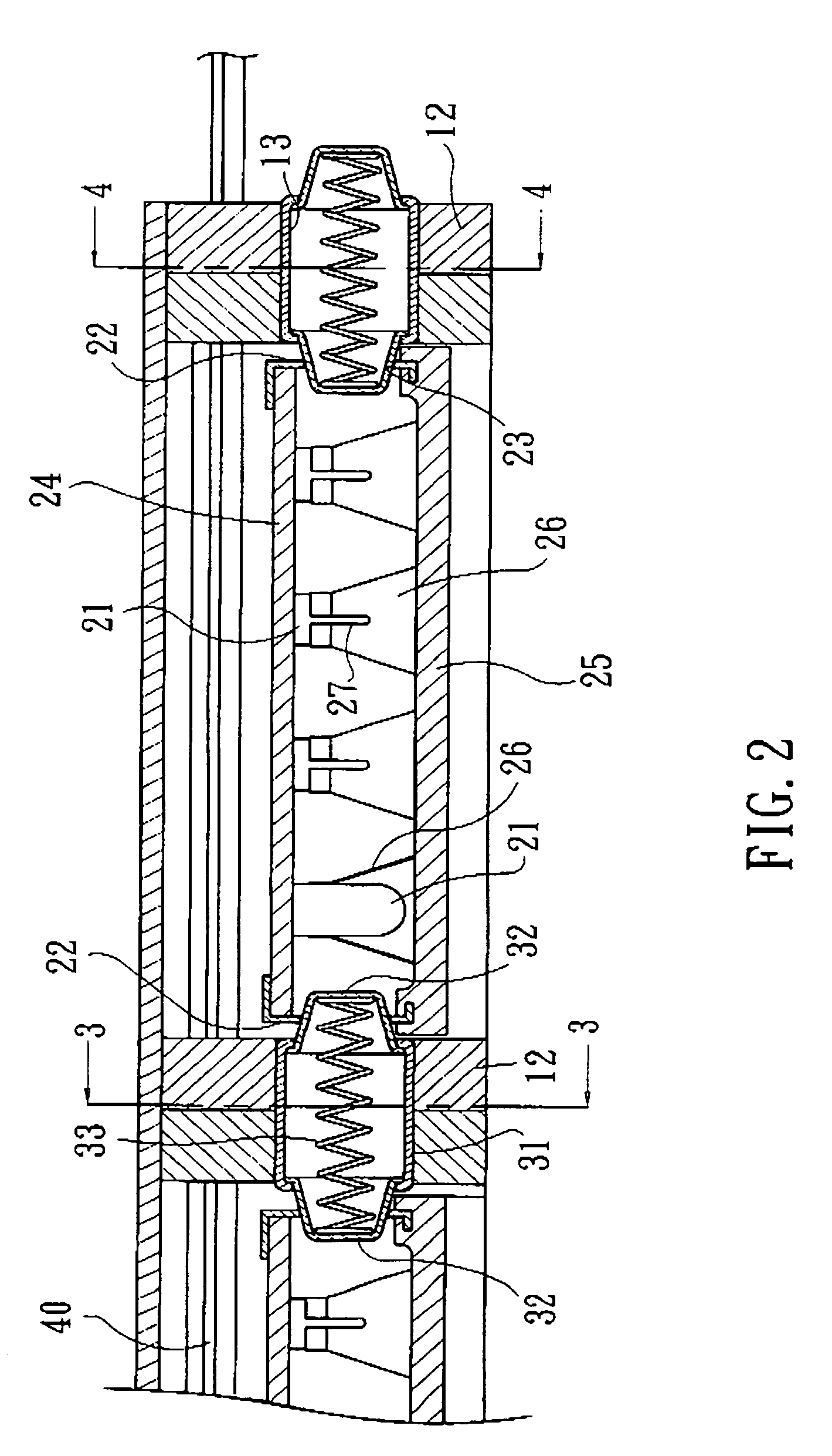
[0018]Please refer to FIGS. 1 and 2 in which an LED lighting with adjustable light projecting direction according to a preferred embodiment of the present invention is shown. As shown, the LED lighting of FIG. 1 includes a lamp holder 10 providing at least one receiving space 11, and at least one lamp bank 20 detachably mounted in the receiving space 11 of the lamp holder 10. Every receiving space 11 on the lamp holder 10 is provided at two ends with a partition 12 each, and the partition 12 is provided at a predetermined position with a first through hole 13. The lamp bank 20 includes at least one LED 21 (see FIG. 2), and has a metal end plate 22 fixedly mounted to each lateral end thereof. The metal end plate 22 is provided at a central area with a second through hole 23.

[0019]A metal cylindrical member 30 is received in the first through holes 13 of two adjoining partitions 12 with two ends of the metal cylindrical member 30 axially protruded from two opposite sides of the two ad...


PUM


Abstract

An LED lighting includes a lamp holder defining at least one receiving space having two partitions provided at two ends thereof, and at least one lamp bank including at least one LED each. The lamp bank is received in the receiving space of the lamp holder by extending two conductive metal cylindrical members located in the two partitions into through holes on two metal end plates at two ends of the lamp bank. The metal cylindrical members are electrically connected to positive and negative electrodes of a power supply, and the two metal end plates serve as two power input ends of the lamp bank. The lamp bank is rotatable about the two metal cylindrical members to adjust the LED light projecting direction while the two metal end plates are in contact with and accordingly electrically connected to the metal cylindrical members to keep the LED in an illuminating state.

Description

FIELD OF THE INVENTION[0001]The present invention relates to an LED lighting with adjustable light projecting direction, in which a lamp bank including at least one LED (light emitting diode) is supported on two pivoting points at two ends of a receiving space in a lamp holder to obtain power supply via the pivoting points and be rotatable about the pivoting points to adjust the light projecting direction of the LED.BACKGROUND OF THE INVENTION[0002]Incandescent bulbs, quartz bulbs, fluorescent bulbs, PL lamps, and mercury lamps are most frequently used on daily lighting fixtures as light sources. Since these bulbs or lamps are mainly designed for illuminating a big space, they are usually mounted on a ceiling. However, there are also many relatively small storing and / or displaying spaces, such as book cases, book shelves, shoe cabinets, wardrobes, showcases and show windows in bakeries and jeweler's shops, etc., that require sufficient light sources to highlight the displayed produc...

Claims


Application Information

Patent Timeline
IPC IPC(8): F21V21/30
CPCF21S4/008F21V14/02F21V17/02F21V21/35F21V19/02F21V21/30F21S2/005F21V11/00F21V17/04F21V19/0085F21W2131/405F21Y2101/02F21Y2103/00F21S4/28F21Y2115/10
Inventor LIN, CHU-HSIEN
Owner LIN CHU HSIEN
Why Eureka
Try Eureka