Physiological Recording Device with Novel and Proprietary Connector

a recording device and connector technology, applied in the field of physiological recording devices with, can solve the problems of endangerment of patients, confusion of electrodes on the part of physicians or technicians applying electrodes, and inability to perform clinical studies, so as to facilitate easy and correct connection, prevent electrode confusion during electrode placement, and facilitate the effect of convenient and correct connection

Active Publication Date: 2020-06-25
NEUROWAVE SYST
View PDF0 Cites 2 Cited by
  • Summary
  • Abstract
  • Description
  • Claims
  • Application Information

AI Technical Summary

Benefits of technology

[0024]Preferably, each electrode has a label on the electrode front, each label being visually distinct from the labels of the other electrodes, and the labels having the characteristics previously described in this disclosure. The feature providing the visual distinction may be color, pattern, reflectivity, or any other visually distinguishable feature or combination of features, but preferably it is color, and so preferably each electrode label has a unique color. The unique color label on each electrode helps the user to identify the desired location and position for each given electrode. Any set of colors may be selected for the electrode, but for example, preferably, the right temple electrode label is orange in color, the reference electrode label is beige in color, the ground electrode label is gray in color, and the left temple electrode label is yellow in color. The difference in colors helps prevent confusion of the electrodes during placement, and further assists in proper and faster electrode placement with the use of an easy-to-use electrode placement map having a color legend. The electrode placement map and legend is preferably provided with the packaging of the electrodes. Furthermore, each electrode lead should preferably echo the color of the corresponding electrode it mates with in order to facilitate easy and correct connection.
[0025]Preferably, all of the electrodes in the set are provided on a single sheet of thin plastic, styrene, or similar material, and each electrode easily peels off. Further preferably, the electrodes are positioned or ordered on the plastic or styrene sheet in roughly the same arrangement they are intended to be applied to the patient, for example, with the right temple electrode on the left of the sheet, and the bridged reference and ground electrodes in the middle of the sheet, and the left temple electrode on the right of the sheet, providing for a helpful spatial correspondence between original packaging placement and eventual placement of the electrodes on the patient.

Problems solved by technology

Proper design of electrodes and their placement is often critical to the reliability, accuracy, and / or repeatability of biopotential measurements and their analysis by the sophisticated monitoring equipment into which their signals are fed; variations in electrode placement or improper electrode placement or improper electrode spacing may mar the study if the analysis equipment is dependent upon proper placement, and may even unnecessarily endanger the patient in the event that a cardiac defibrillation shock is applied to the patient during consciousness monitoring.
This similarity in some cases can result in electrode confusion on the part of the physician or technician applying the electrodes.
Common mistakes in electrode placement include a mix-up between left-side and right-side electrode placement on the patient, a mix-up between signal and ground electrodes on the patient, incorrect placement of the electrodes on the patient in relation to the optimal or desired placement sites, placement of electrodes too near to each other or too far from each other, or placement of the electrodes in wrong or sub-optimal orientations with respect to each other.

Method used


Image

  • Physiological Recording Device with Novel and Proprietary Connector
  • Physiological Recording Device with Novel and Proprietary Connector
  • Physiological Recording Device with Novel and Proprietary Connector

Examples


Embodiment Construction

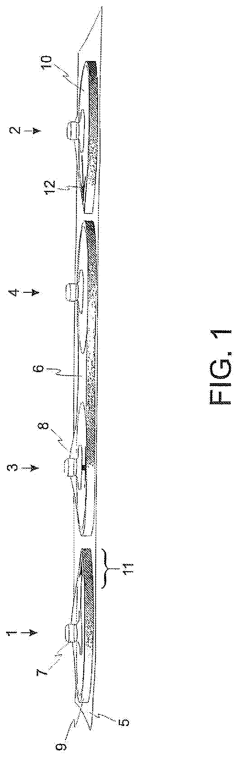
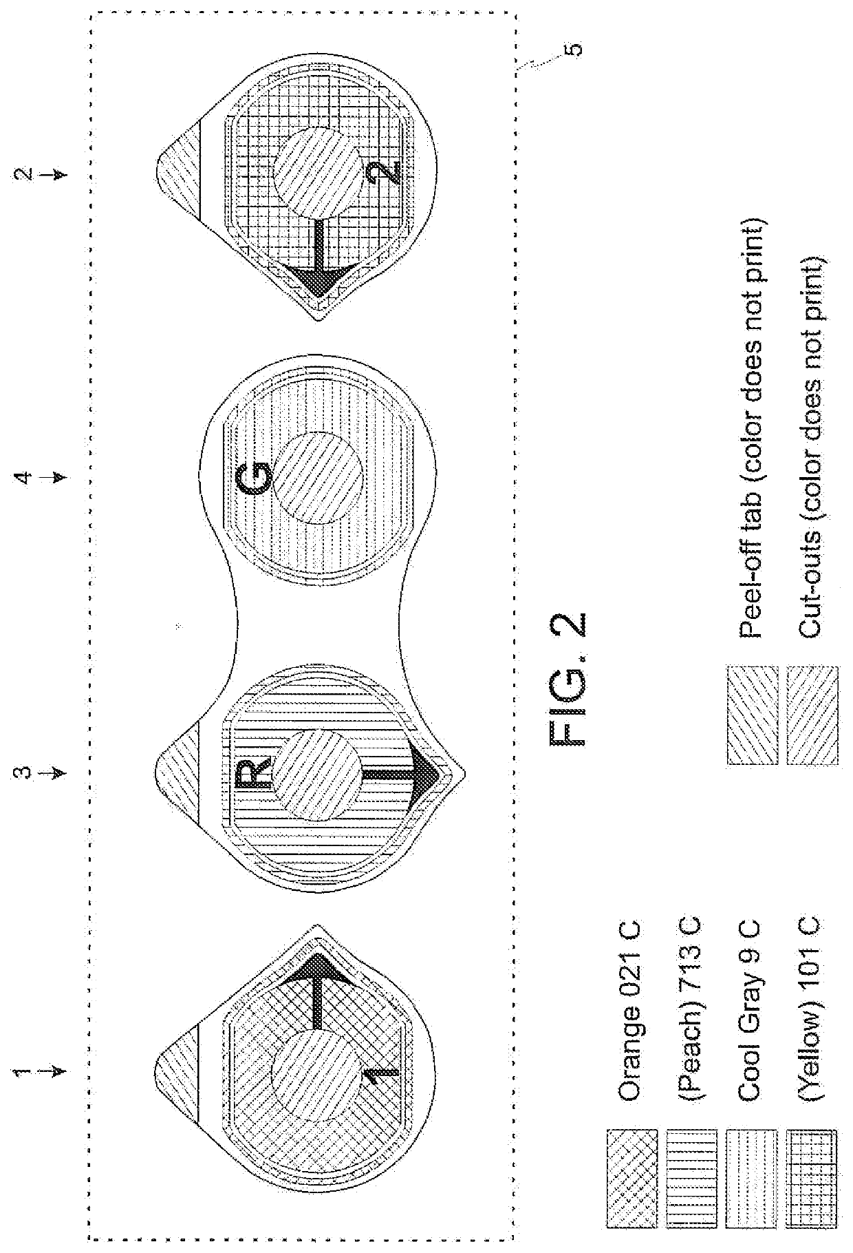
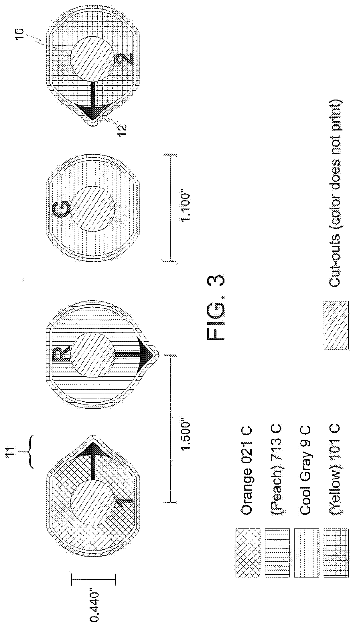
[0056]A preferred embodiment of the invention is illustrated and described. Four thin prepared electrodes come as a package as shown in FIG. 1. The right temple electrode 1 comes placed on the left side of a thin plastic, or similar material, backing sheet 5, and the left temple electrode 2 comes placed on the right side of the backing sheet. The reference electrode 3 and ground electrode 4 are conjoined by an insulating bridge 6. Each electrode has its own independent connector 7. As illustrated, the connectors are standard-size metal button or snap connectors, but as previously described, the connectors can be of any type or form factor known in the art. The right temple electrode, reference electrode and left temple electrode each have upward-pointing handling tabs 8 on their top sides. The handling tab is one and the same material as the foam insulating body structure 9 of the electrode with the exception that the handling tab is not backed with an adhesive like the rest of the ...


PUM


Abstract

Electrodes for use in electroencephalographic recording, including consciousness and seizure monitoring applications, have novel features that speed, facilitate or enforce proper placement of the electrodes, including aligning tabs and arrowed aligning juts, color coding, and an insulating bridge between reference and ground electrodes which ensures a safe application distance between the conductive regions of the two electrodes in the event of cardiac defibrillation or to prevent shorting between the adjacent electrodes by preventing the conductive path to be shared. A method of using a set of four such electrodes is also disclosed.

Description

CROSS-REFERENCE TO RELATED APPLICATIONS[0001]This application claims priority as a continuation-in-part to U.S. patent application Ser. No. 14 / 533,473 filed on Nov. 5, 2014, which was a continuation of U.S. patent application Ser. No. 13 / 942,669 filed on Jul. 15, 2013, and which issued as U.S. Pat. No. 8,909,317 on Dec. 9, 2014, and which was a continuation-in-part of U.S. patent application Ser. No. 13 / 110,533, which was filed on May 18, 2011 and which issued as U.S. Pat. No. 8,515,522 on Aug. 20, 2013, and which was a non-provisional application of U.S. Provisional Patent application, Ser. No. 61 / 348,154, which was filed on May 25, 2010.BACKGROUND OF THE INVENTION(1) Field of the Invention[0002]The present invention relates to sensors for fast and easy deployment in electroencephalogram acquisition and monitoring applications, including consciousness and seizure monitoring. The present invention further relates to electrodes for measuring biopotentials. The present invention furth...

Claims


Application Information

Patent Timeline
Patent Type & Authority Applications(United States)
IPC IPC(8): A61B5/0478A61B5/00
CPCA61B5/0478A61B5/4064A61B5/4094A61B5/684A61B5/6814A61B5/04842A61B5/0006A61B5/291A61B5/4821A61B5/6833A61B2562/046A61B5/378
Inventor BIBIAN, STÉPHANEZIKOV, TATJANA
Owner NEUROWAVE SYST
Why Eureka
Try Eureka