Unlock instant, AI-driven research and patent intelligence for your innovation.

Door handle device

Inactive Publication Date: 2007-05-01
AISIN SEIKI KK
View PDF21 Cites 39 Cited by
  • Summary
  • Abstract
  • Description
  • Claims
  • Application Information

AI Technical Summary

Problems solved by technology

Thus, wiring structure between the antenna and the oscillating circuit cannot be simplified, and noise may be generated due to the complicated wiring structure.

Method used


Image

  • Door handle device
  • Door handle device
  • Door handle device

Examples


Embodiment Construction

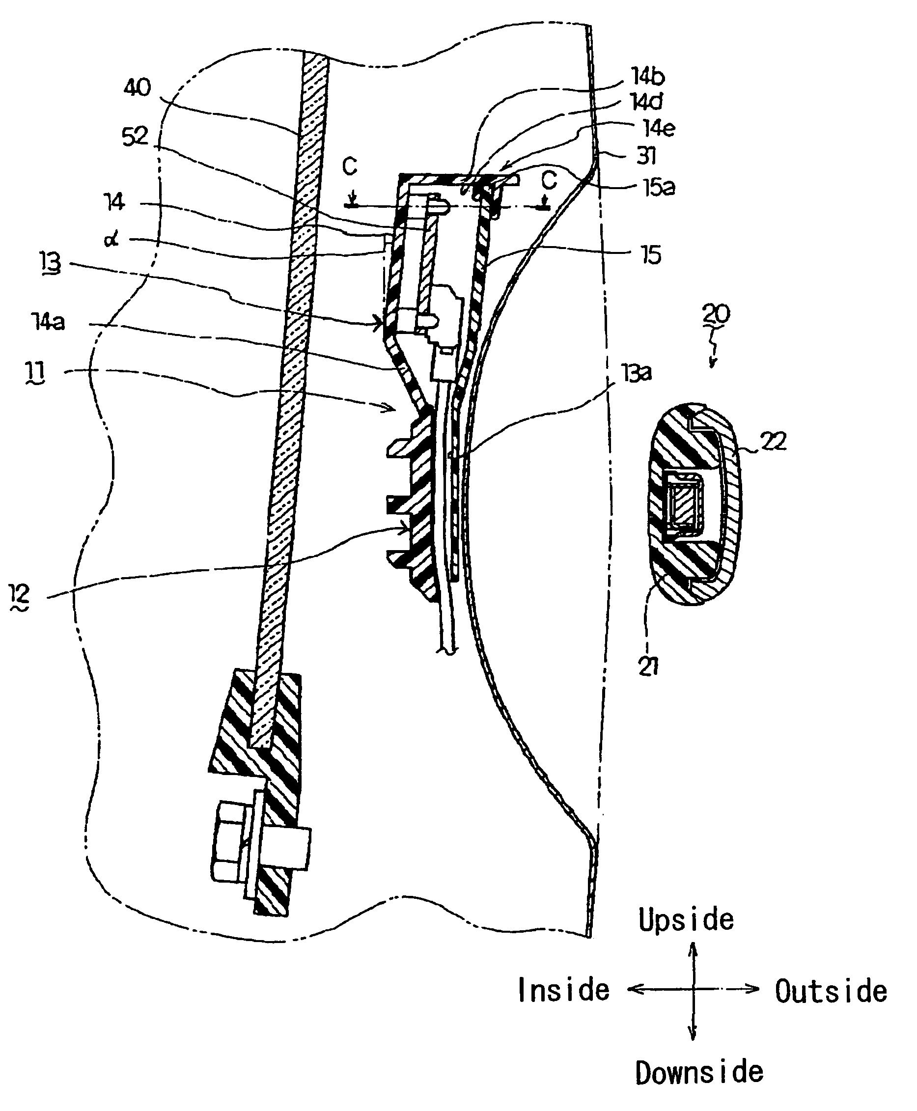
[0017]Hereinafter, an embodiment of the present invention is described with reference to FIGS. 1–8. In this embodiment, a door handle device 10 according to the present invention is applied to a smart entry system 50 (hereinafter referred to as a system 50). The system 50 is a door locking / unlocking system in which a vehicle door being in a locked state is switched to an unlocked state when an owner of a vehicle (hereinafter referred to as a user) is close to the vehicle and a hand of the user approaching the door handle device 10 is detected.

[0018]First, the system 50 is briefly explained with reference to FIG. 1 and FIG. 2. The system 50 includes a primary transmitting antenna 54 (an electrical component) communicating with the outside of the vehicle and a secondary transmitting antenna 56 communicating with the inside of the vehicle. The primary transmitting antenna 54 is provided within the door handle device 10 (shown in FIG. 3) mounted to a vehicle door 30 (shown in FIG. 3), a...


PUM


Abstract

A door handle device includes a frame fixed to the inside of an outer panel of a vehicle door and a grip provided on the frame from the outside of a vehicle and including an electrical component. The frame is integrally provided with a circuit electrically connected to the electrical component. The door handle device further includes a chassis integrally formed with the frame, and the circuit is provided within the chassis.

Description

CROSS REFERENCE TO RELATED APPLICATIONS[0001]The application is based on and claims priority under 35 U.S.C. § 119 with respect to a Japanese Patent Application 2002-284172, filed on Sep. 27, 2002, the entire content of which is incorporated herein by reference.FIELD OF THE INVENTION[0002]This invention generally relates to a door handle device. More particularly, this invention pertains to a door handle device applied to a vehicle door.BACKGROUND OF THE INVENTION[0003]For example, a known door handle device is disclosed in a Japanese Patent Laid-open Publication No. 2002-30844. This door handle device includes a handle frame and a handle grip. The handle frame is fixed to an outer panel of a vehicle door. The handle grip is provided on the handle frame from the outside of a vehicle through the outer panel, and electrical components are included in the handle grip.[0004]In the door handle device, the handle grip includes an antenna as one of the electrical components. The antenna tr...

Claims


Application Information

Patent Timeline
IPC IPC(8): E05B3/00E05B1/00B60J5/04B60R16/02E05B49/00E05B81/54E05B81/78E05B85/16
CPCE05B81/76Y10S292/25Y10T70/5889Y10T70/5973Y10T292/57
Inventor KOBAYASHI, NORIKAZUMURAKAMI, YUICHIAOKI, KOJIFUKUNAGA, KATSUTOSHI
Owner AISIN SEIKI KK