Echo cancellation/suppression and double-talk detection in communication paths

a communication path and double-talk technology, applied in the field of telecommunications, can solve the problems of error signals, inability to deal with non-linear effects, and degrade voice quality over the communication channel, so as to maintain voice quality, avoid switching effects, and maintain voice quality

Active Publication Date: 2007-05-01
MITEL +1
View PDF10 Cites 28 Cited by
  • Summary
  • Abstract
  • Description
  • Claims
  • Application Information

AI Technical Summary

Benefits of technology

[0025]a processor receiving said estimated echo signals and said residual echo error signals, said processor determining the power level of the transmitted signals supplied to said communication path generating leaky masks, said leaky masks being generated as a function of the determined power level of said transmitted signals and the noise level of received echo signals, said leaky masks being applied to the residual echo error signals thereby to suppress partially said residual echo error signals.
[0026]The present invention provides advantages in that since the echo suppressor generates adaptive leaky masks, echo suppression is achieved while maintaining voice quality and avoiding switching effects in the presence of background noise. Also, since echo suppression is switched off in the presence of double-talk, voice quality is maintained in double-talk situations.

Problems solved by technology

However, if the delays in the network are significant, echo signals in the network due to acoustic coupling will noticeably degrade voice quality over the communication channel.
Differences between the estimated echo signals and the actual echo signals result in error signals, which are fed back to the echo canceller.
Unfortunately, since the algorithm executed by the echo canceller is linear, the echo canceller cannot deal with non-linear effects and can only converge to a transfer function that approximates the echo signals.
Although this echo suppressor works well to suppress echo, since the number of least significant bits in the masks that are set to one to leak echo signals is static, switching effects that degrade voice quality still result.
Also, since the echo suppressor is active all the time with the number of zeros in the masks changing depending on the power level of the signals broadcast by the handset speaker, the echo suppressor degrades speech quality during double-talk situations.

Method used


Image

  • Echo cancellation/suppression and double-talk detection in communication paths
  • Echo cancellation/suppression and double-talk detection in communication paths
  • Echo cancellation/suppression and double-talk detection in communication paths

Examples


Embodiment Construction

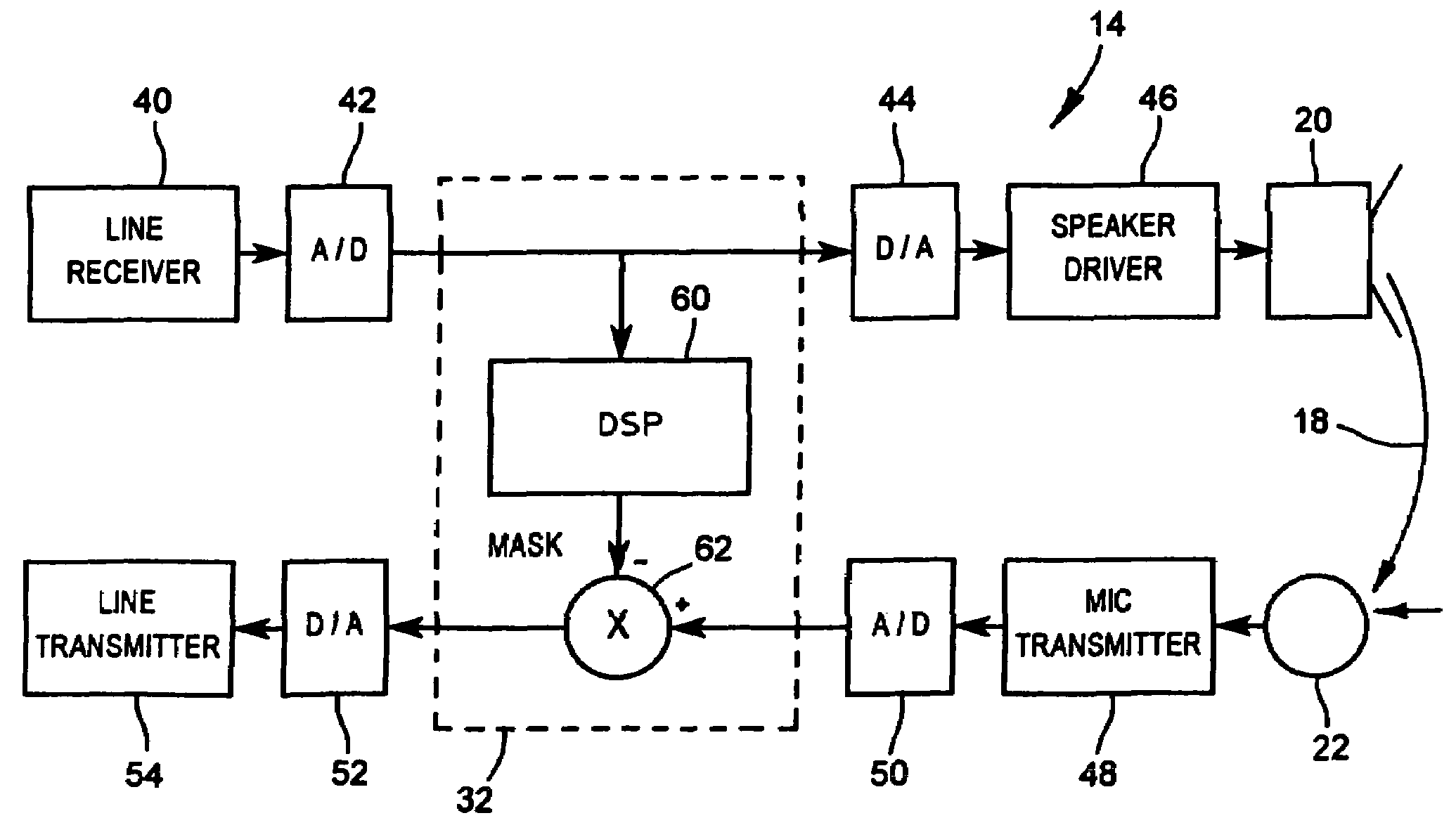
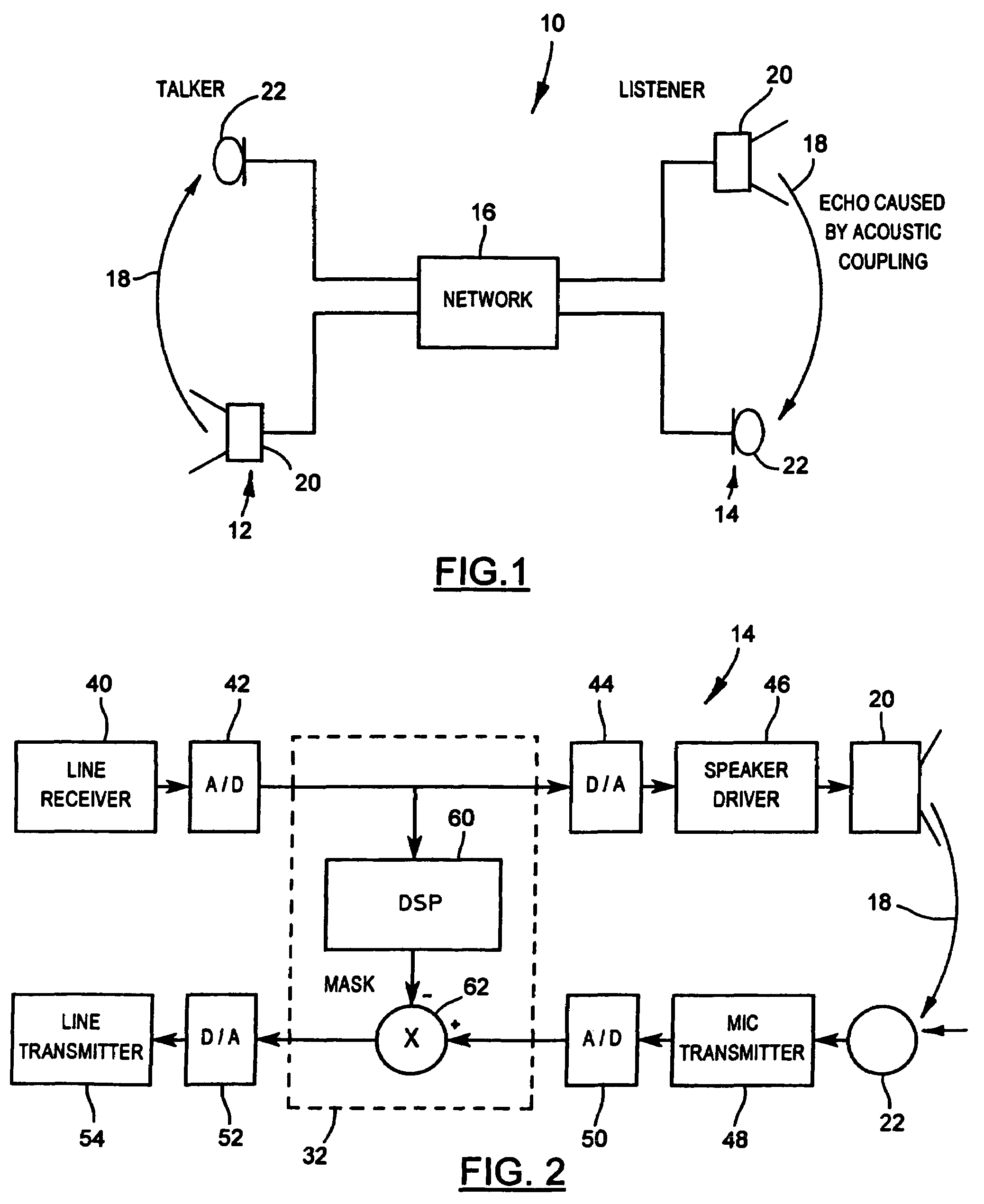
[0032]Turning now to FIG. 1, a communication channel established between a pair of telephone devices 12 and 14 over a network 16 is shown and is generally identified by reference numeral 10. As can be seen, when a communication channel is established between the telephone devices 12 and 14, acoustic signals 18 broadcast by the handset speaker 20 of receiving telephone device 14 are acoustically coupled to the handset microphone 22 of the telephone device 14. The echo signals picked up by the handset microphone 22 as a result of the acoustic coupling cause echoes in the network 16, which degrade voice quality. If the delay in the network 16 is long, such as for example 150 ms, which may be caused by voice packetization and local area network (LAN) propagation delays, echoes in the network 16 as a result of the acoustic coupling become audible thereby detracting from voice quality.

[0033]To suppress adaptively echo signals picked up by the handset microphone 22 as a result of acoustic ...


PUM


Abstract

A method of suppressing an echo signal in a communication path such as acoustic coupling between a speaker and a microphone in a telephone device handset includes the steps of monitoring a transmitted signal supplied to the communication path to determine an attribute thereof; generating a leaky mask based on the determined attribute and an attribute of a received echo signal; and partially cancelling the received echo signal using the leaky mask.

Description

FIELD OF THE INVENTION[0001]The present invention relates generally to telecommunications and in particular to echo cancellation / suppression and double-talk detection in communication paths.BACKGROUND OF THE INVENTION[0002]Acoustic coupling in telephone device handsets is common and occurs when signals broadcast by the speaker of a telephone device are coupled to the microphone of the same telephone device. This acoustic coupling causes echo signals in the network over which the communication channel is established. The acoustic suppression of signals broadcast by the handset speaker before they are picked up by the handset microphone is variable and depends on a number of factors, such as for example, the pressure exerted on the user's ear by the handset speaker and how well the handset speaker seals the user's ear. The loss in power of these signals as a result of acoustic suppression can vary from about −50 db to as low as −24 db when the telephone device handset is placed on a h...

Claims


Application Information

Patent Timeline
Patent Type & Authority Patents(United States)
IPC IPC(8): H04M9/08H04B3/23
CPCH04B3/23H04B3/234H04M9/082
Inventor POPOVIC, MIRJANASCHULTZ, DIETER
Owner MITEL
Why Eureka
Try Eureka