
Coded-array technique for obtaining depth and other position information of an observed object

a coded array and object technology, applied in the field of sensor systems, can solve the problems of requiring the projection of a moving beam or pattern of light, affecting the reliability of the apparatus, and requiring only one depth map of the scene over a period of tim

Active Publication Date: 2007-05-01
MICROSOFT TECH LICENSING LLC
View PDF3 Cites 162 Cited by
  • Summary
  • Abstract
  • Description
  • Claims
  • Application Information

AI Technical Summary

Benefits of technology

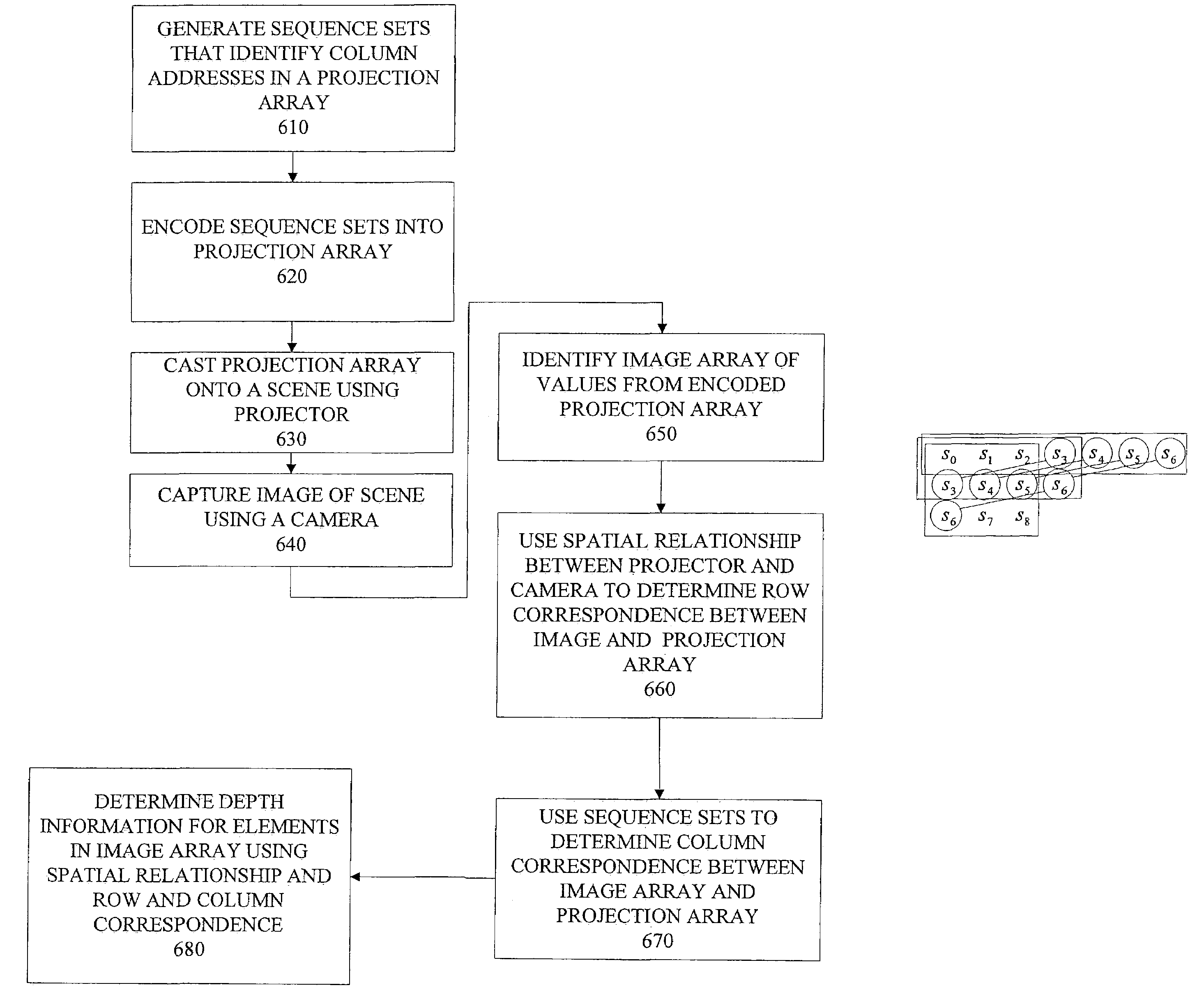
[0006]In another embodiment, a coded light pattern can be created on a scene, by creating a sequence of values that include a plurality of subsequences. Each subsequence may identify one or more elements of a projection array. A value may be assigned to a characteristic in a set of optically distinguishable characteristics. Then, light may be projected a pattern in order to create at least a portion of the pattern on the scene. The sequence is encoded in

Problems solved by technology

Their most important drawback, on the other hand, is that they require the projection of a moving beam or pattern of light onto the observation scene.
The need for a moving light pattern implies some mechanical moving component, which adds to the cost or detracts from the reliability of the apparatus.
Even more importantly, the need to scan the scene with a moving light beam, or to project sequences of light patterns, means that one single depth map of the scene can only be captured over a period of time, often several seconds, and in some instances even minutes.
As a result, structured-light systems are often poorly suited for real-time applications, in which the position and configuration of the object of interest may change rapidly.

Method used


Image

  • Coded-array technique for obtaining depth and other position information of an observed object
  • Coded-array technique for obtaining depth and other position information of an observed object
  • Coded-array technique for obtaining depth and other position information of an observed object

Examples


Embodiment Construction

[0022]Embodiments of the invention describe a coded-array technique for obtaining depth and other position information for an observed object. In the following description, for the purposes of explanation, numerous specific details are set forth in order to provide a thorough understanding of the present invention. It will be apparent, however, that the present invention may be practiced without these specific details. In other instances, well-known structures and devices are shown in block diagram form in order to avoid unnecessarily obscuring the present invention.

[0023]Overview

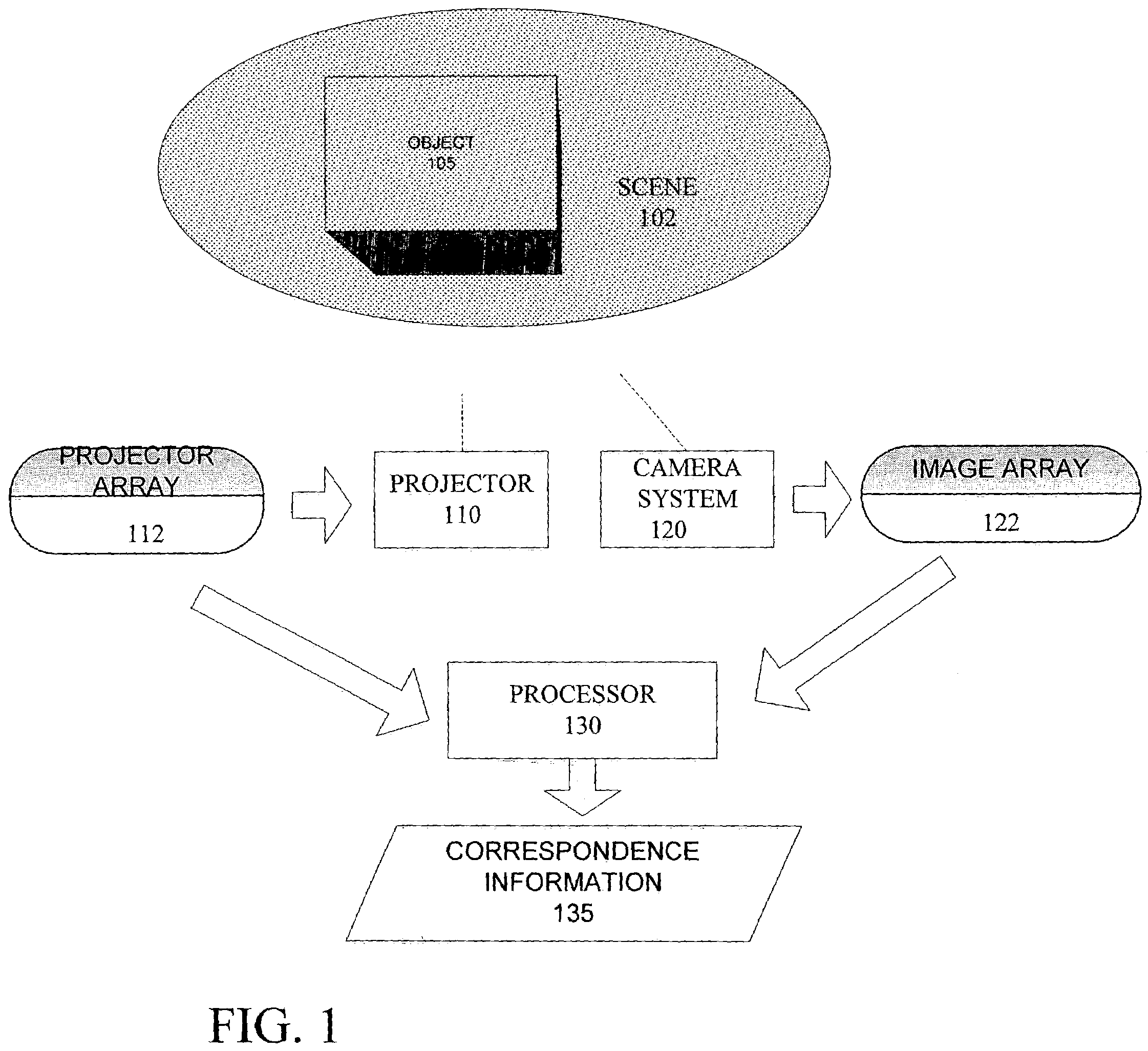
[0024]Embodiments of the invention provide for determining information about discrete points on an observed object by analyzing an image of the object and referencing the image to known characteristics of light projected onto the object. In one embodiment, light is coded to provide discrete identifiable elements. The coded light is then projected onto an object or scene. A camera or similar sensing apparatu...


PUM


Abstract

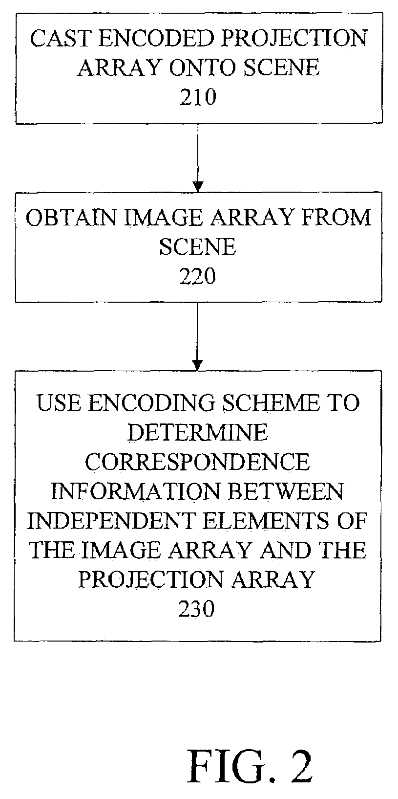
A projection array is provided that comprises a plurality of discrete projection elements. An image array is obtained of a scene with the light projected onto it that is coded using the projection array. Correspondence information is determined for each element in the image array, where the correspondence information can be used to determine which of the plurality of elements in the projection array corresponds to a particular image element. The determination of correspondence information for each element in the image array can be made independently of correspondence information for other elements in the image array.

Description

RELATED APPLICATIONS[0001]This application claims benefit of priority to Provisional U.S. Patent Application No. 60 / 390,232, filed Jun. 19, 2002, entitled “A Coded-Grid Depth Sensor,” and naming Carlo Tomasi as an inventor. The aforementioned priority application is hereby incorporated by reference in its entirety for all purposes.FIELD OF THE INVENTION[0002]The present invention relates to sensor systems that observe objects. In particular, the present invention relates to a method and apparatus for obtaining depth and other position information of an observed object.BACKGROUND OF THE INVENTION[0003]Three-dimensional sensor systems are increasingly being used in a wide-array of applications. In one general application, a three-dimensional sensor system is used to determine the shape and / or features of an object positioned in a scene of the sensor system's view. Many methods have been proposed for implementing sensor systems for sensing shapes and features in three-dimensions. Such ...

Claims


Application Information

Patent Timeline
IPC IPC(8): G06K9/00G01B11/25
CPCG01B11/25
Inventor TOMASI, CARLO
Owner MICROSOFT TECH LICENSING LLC
Learn More