Medical observation system and processor
a technology of observation system and processor, applied in the field of medical observation system, to achieve the effect of reducing processing load, executing light amount control more quickly, and accurately judging the state of medical probes
- Summary
- Abstract
- Description
- Claims
- Application Information
AI Technical Summary
Benefits of technology
Problems solved by technology
Method used
Image
Examples
first embodiment
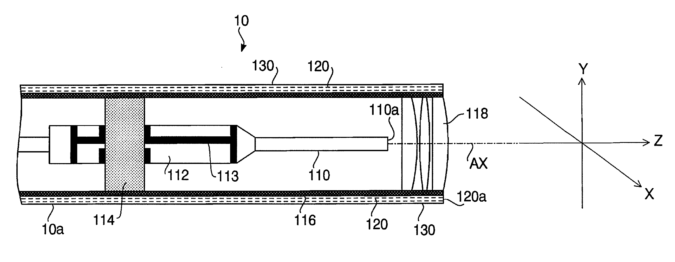
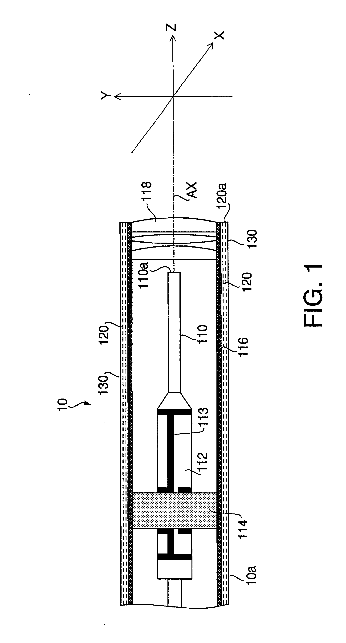
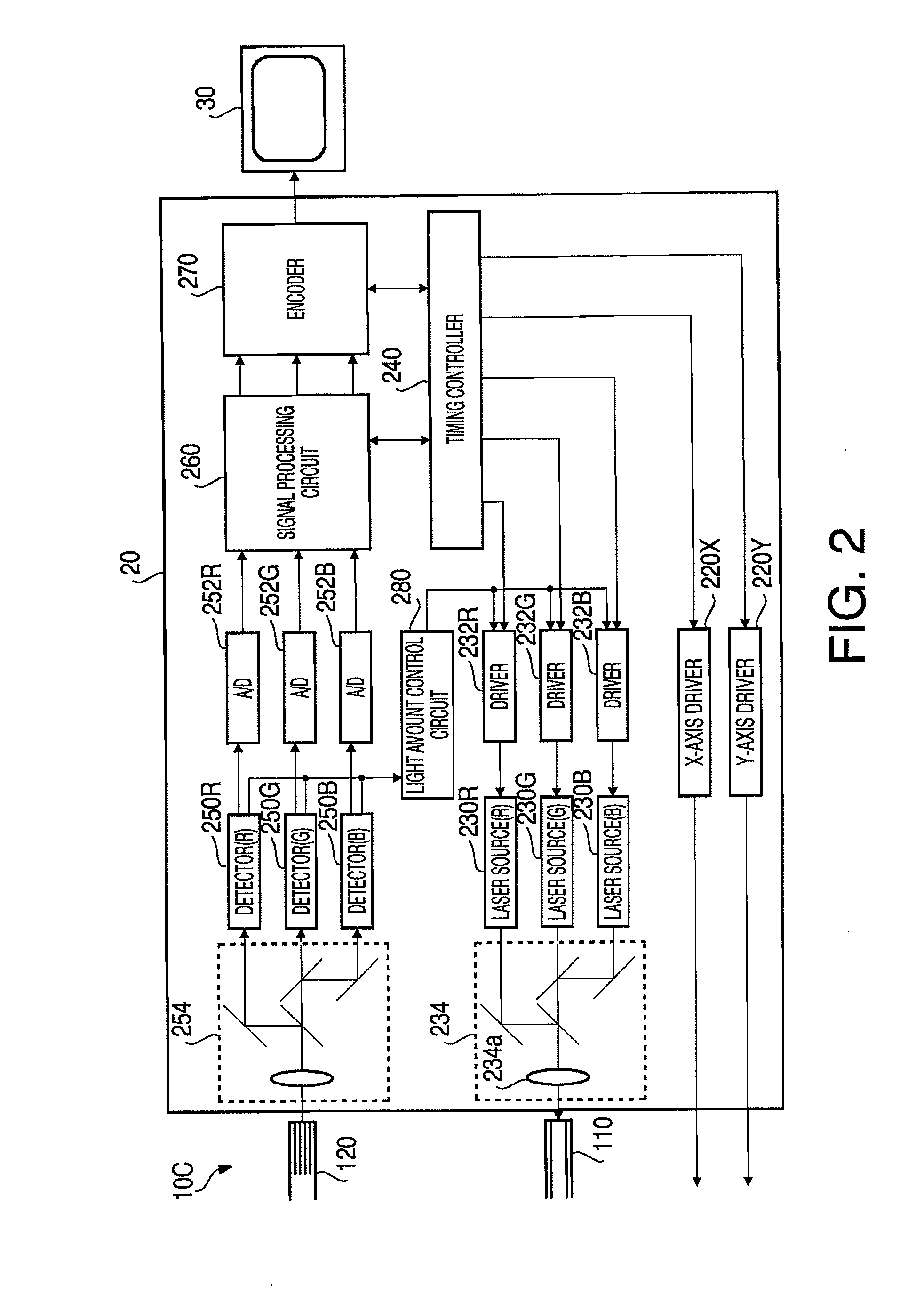
[0035]FIG. 1 illustrates an inner configuration of a tip part of a scanning medical probe 10 according to a first embodiment of the invention. FIG. 2 is a block diagram illustrating a configuration of a processor 20 to which the scanning medical probe 10 is connected. In FIG. 2, a part of the scanning medical probe 10 and a monitor 30 are also illustrated for clearly indicating connection relationship between the processor 20, the scanning medical probe 10 and the monitor 30. A monitor having a general configuration known in the art may be used as the monitor 30. The scanning medical probe 10, the processor 20 and the monitor 30 configure a medical observation system 1.
[0036]First, the configuration of the scanning medical probe 10 is explained with reference to FIG. 1. The scanning medical probe 10 includes an insertion unit 10a, a grip part 10b (see FIG. 10) to be gripped by an operator and a joint part 10c (see FIG. 2) to be electrically and optically connected to the processor 2...
second embodiment
[0069]Hereafter, a second embodiment of the invention is explained. Since a medical observation system according to the second embodiment has substantially the same configuration as those of the first embodiment shown in FIGS. 1 and 2 and the flow of the observation explained in the first embodiment can also be applied to the second embodiment, in the following explanation focuses on the feature of the second embodiment (i.e., a light amount control process executed by the light amount control circuit 280). In the following, to elements, which are substantially the same as those of the first embodiment, the same reference numbers are assigned, and explanations thereof will not be repeated.
[0070]FIG. 7 is a flowchart illustrating the light amount control process according to the second embodiment. Steps S201 to S206 in the light amount control process according to the second embodiment are the same as steps S101 to S106 of the first embodiment. That is, as in the case of the first em...
third embodiment
[0077]Hereafter, a third embodiment of the invention is explained. Since a medical observation system according to the third embodiment has substantially the same configuration as those of the first embodiment shown in FIGS. 1 and 2 and the flow of the observation explained in the first embodiment can also be applied to the third embodiment, in the following explanation focuses on the feature of the third embodiment (i.e., a light amount control process executed by the light amount control circuit 280). In the following, to elements, which are substantially the same as those of the first embodiment, the same reference numbers are assigned, and explanations thereof will not be repeated.
[0078]FIG. 9 is a flowchart illustrating the light amount control process according to the third embodiment. First, an average intensity of an image corresponding to one frame is calculated based on the analog signals detected by the detectors 250R, 250G and 250B (step S301). Then, the light amount con...
PUM
 Abstract
Description
Claims
Application Information
 - R&D
- Intellectual Property
- Life Sciences
- Materials
- Tech Scout
- Unparalleled Data Quality
- Higher Quality Content
- 60% Fewer Hallucinations
Browse by: Latest US Patents, China's latest patents, Technical Efficacy Thesaurus, Application Domain, Technology Topic, Popular Technical Reports.
© 2025 PatSnap. All rights reserved.Legal|Privacy policy|Modern Slavery Act Transparency Statement|Sitemap|About US| Contact US: help@patsnap.com


