microscope and a fluorescent observation method using the same

a fluorescent observation and microscope technology, applied in the field of microscopes and fluorescent observation methods, can solve the problems of reducing spatial resolution, adversely affecting the cell under observation, and destroying the effect of excitation light having an ultraviolet wavelength band

Inactive Publication Date: 2011-10-06
JAPAN SCI & TECH CORP
View PDF6 Cites 30 Cited by
  • Summary
  • Abstract
  • Description
  • Claims
  • Application Information

AI Technical Summary

Benefits of technology

[0053]According to the microscope of the present invention, since the fluorescent observation area of the microscope is determined based on the image information and the dynamic model of the object under observation, fluorescent observation can be performed automatically.
[0054]According to the fluorescent observation method using the microscope of the present invention, s

Problems solved by technology

(i) Excitation light having an ultraviolet wavelength band is harmful to cells; and
However, the method in (

Method used


Image

  •  microscope and a fluorescent observation method using the same
  •  microscope and a fluorescent observation method using the same
  •  microscope and a fluorescent observation method using the same

Examples


embodiment 1

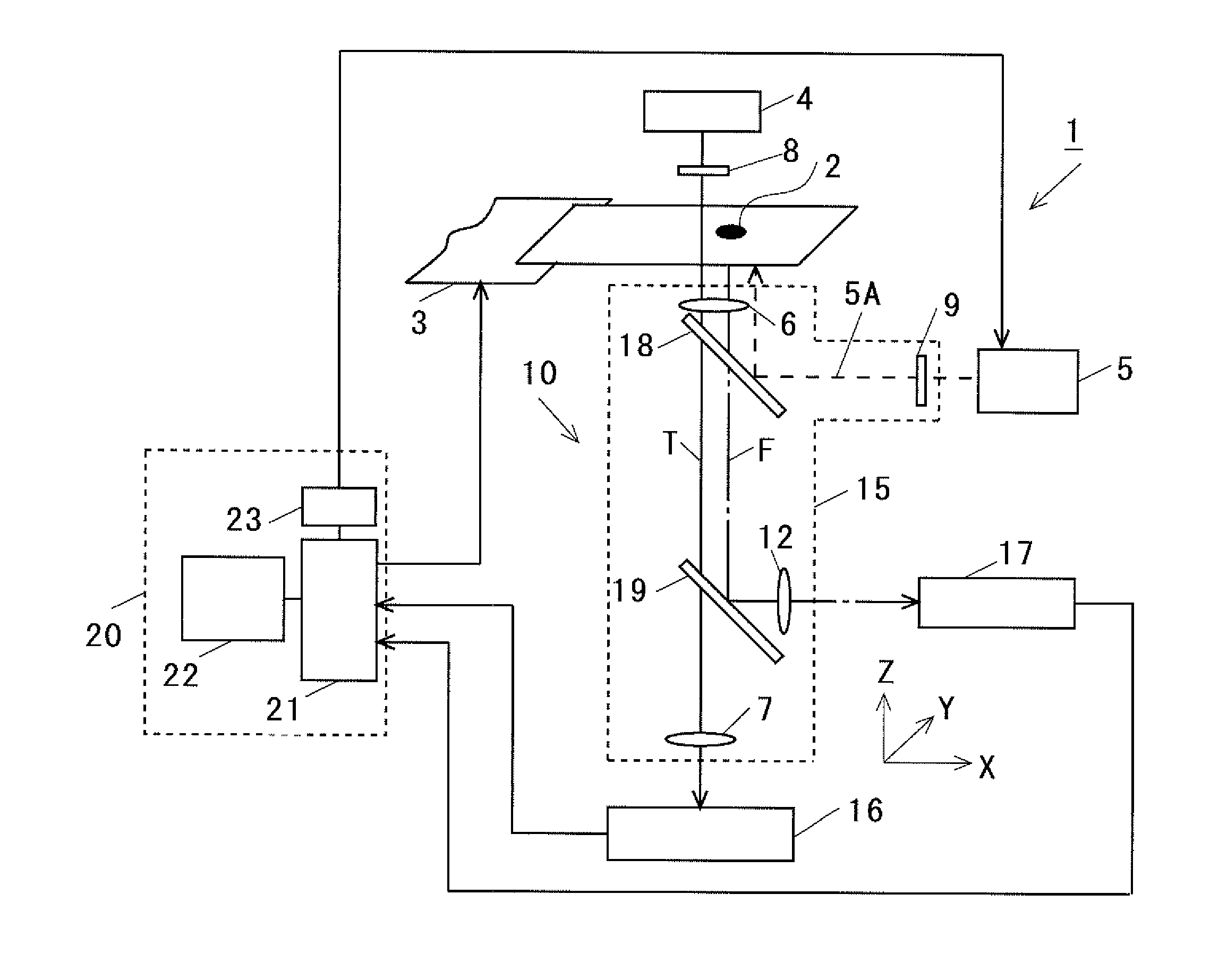
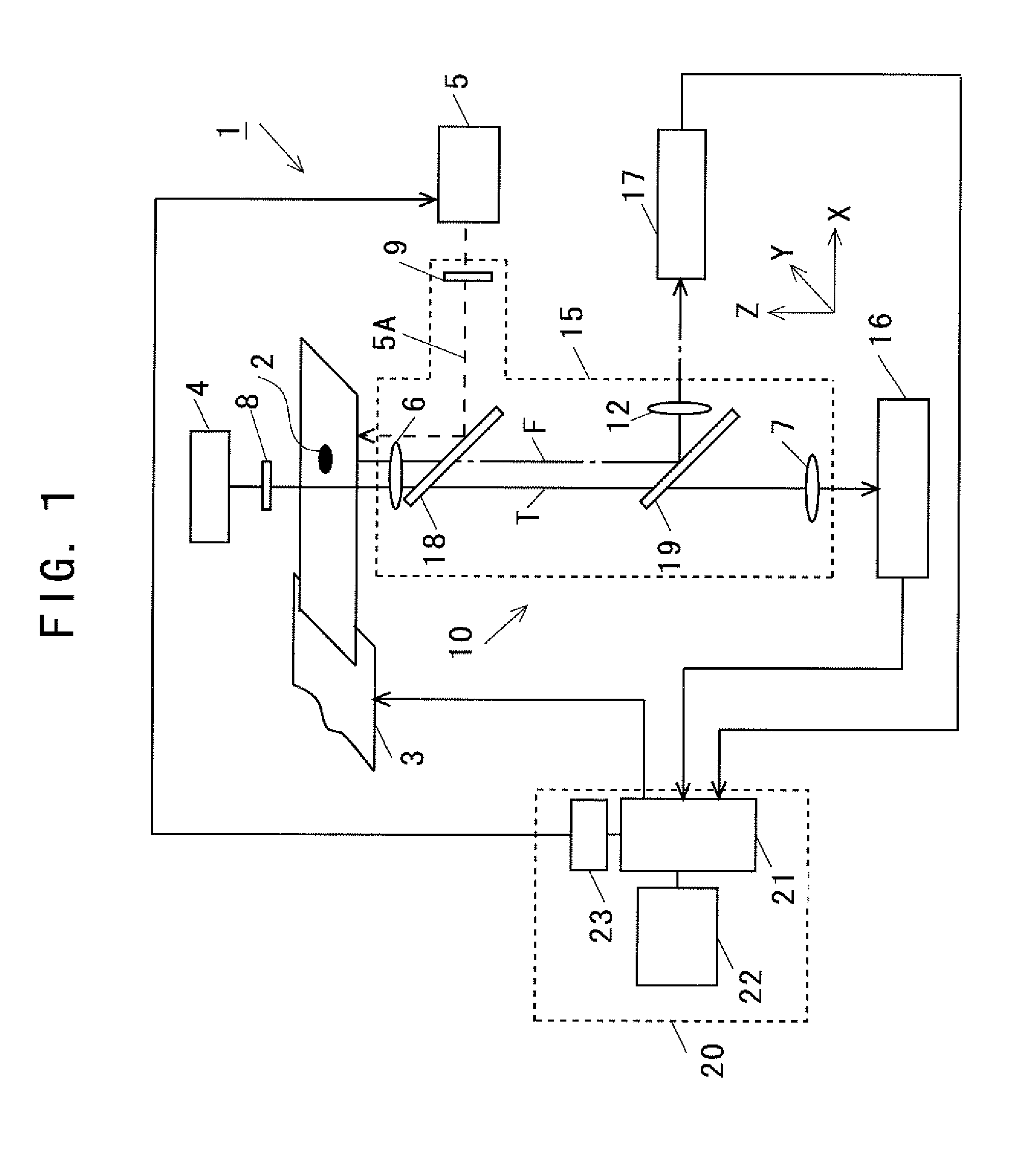
[0071]FIG. 1 illustrates a diagram showing the configuration of a microscope 1 in accordance with the Embodiment 1 of the present invention. A microscope 1 in accordance with the Embodiment 1 comprises: a stage 3 for carrying and freely moving an object under observation 2; an optical system 10; and a control part 20 for controlling the position, etc. of the stage 3.

[0072]The optical system 10 comprises: an illumination light source 4 for irradiating illumination light to the object under observation 2 to detect an image and a position of the object under observation 2; an excitation light source 5 for irradiating excitation light for exciting fluorescent light generated from the object under observation 2; an optical column part 15 containing optical components for forming a light path of a transmission light T obtained from the object under observation 2 through irradiation from the illumination light source 4, a light path for introducing the excitation light 5A into the object u...

embodiment 2

[0181]FIG. 4 illustrates a diagram showing the configuration of the microscope 30 in accordance with the Embodiment 2 of the present invention. The configuration of the microscope 30 is the same as that of the microscope 1 except that an objective lens drive part 32 is provided to move the objective lens 6 in the direction of the optical axis of the transmission light T, namely in the direction of Z-axis. The objective lens drive part 32 is controlled by the control part 20. The objective lens drive part 32 can be configured using a driving part such as piezoelectric element. Description of the rest of the configuration will be omitted because it is the same as that of the microscope 1.

embodiment 3

[0182]FIG. 5 illustrates a diagram showing the configuration of the microscope 35 in accordance with the Embodiment 3 of implementation of the present invention.

[0183]The configuration of the microscope 35 is the same as that of the microscope 1 except that a transmission light imaging lens drive part 37 is provided to move the imaging lens 7 on the side of the image information detecting part 16 in the direction of the optical axis (direction of Z-axis). The imaging lens drive part 37 is controlled by the control part 20. The imaging lens drive part 37 may be configured using a drive part such as piezoelectric element. Description of the rest of the configuration will be omitted because it is the same as that of the microscope 1.


PUM


Abstract

A microscope capable of controlling the position and fluorescent recording of an object under observation such as cells is provided with the fluorescent observation method using the microscope. The microscope 1 comprises: a stage 3 on which the object under observation 2 is placed; an illumination light source 4 for the object under observation 2; an excitation light source 5 for exciting fluorescent light F to the object under observation 2; an image information detecting part 16 for detecting the image information formed with the light T generated at the object under observation 2; a fluorescent image information detecting part 17 for detecting the fluorescent image information formed with fluorescent light F; and a control part 20, which determines the fluorescent observation area of the object under observation 2 based on the dynamic model of the object under observation 2 and its image information entered from the image information detecting part 16, and then obtains the image information of the object under observation 2 entered from the image information detecting part 16 and the fluorescent image information entered from the fluorescent image information detecting part 17 at specified interval within the fluorescent observation area.

Description

TECHNICAL FIELD[0001]The present invention relates to a microscope used for fluorescent observation of body tissues, etc. and a fluorescent observation method for objects to be observed using the same.BACKGROUND ART[0002]Observation of body tissues and intracellular ions and molecules is an essential technique used in the field of molecular biology. An optical microscope is mainly used to observe body tissues. A laser confocal microscope is used to observe a part of a living cell by irradiating light to that part while moving the position of irradiation.[0003]Major observation techniques of the optical microscope include a fluorescent observation method. In this method, intracellular ions and molecules of body tissues are colored with a fluorescent dye, an excitation light is irradiated to the fluorescent dye, and then the fluorescent light emitted from the excited fluorescent dye is observed.[0004]Since the wavelengths of the fluorescent light and the excitation light are not ident...

Claims


Application Information

Patent Timeline
IPC IPC(8): H04N7/18
CPCG01N21/6458G02B21/0076G02B21/34G02B21/26G02B21/0088G02B21/16
Inventor IGARASHI, YASUNOBUOBARA, TAKESHIDEGUCHI, YUKISUZUKI, TAKESHIHASHIMOTO, KOICHI
Owner JAPAN SCI & TECH CORP
Why Eureka
Try Eureka