Apparatus and method for facilitating the connection of tubulars using a top drive

a top drive and tubular technology, applied in the direction of drilling pipes, drilling casings, borehole/well accessories, etc., can solve the problems of inconvenient connection of tubulars, etc., to achieve the effect of reducing these problems

Inactive Publication Date: 2007-05-08
WEATHERFORD TECH HLDG LLC
View PDF807 Cites 73 Cited by
  • Summary
  • Abstract
  • Description
  • Claims
  • Application Information

AI Technical Summary

Benefits of technology

[0008]The apparatus disclosed therein is bulky, cumbersome and awkw

Problems solved by technology

It has been observed that sections or stands of tubulars are often not as uniform as desired.
In particular, the sections or stands of tubula

Method used


Image

  • Apparatus and method for facilitating the connection of tubulars using a top drive
  • Apparatus and method for facilitating the connection of tubulars using a top drive
  • Apparatus and method for facilitating the connection of tubulars using a top drive

Examples


Embodiment Construction

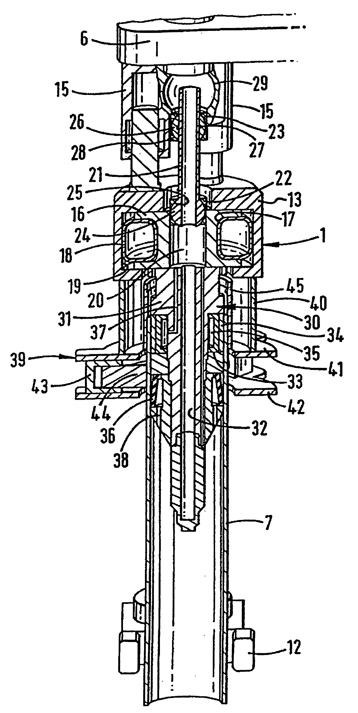
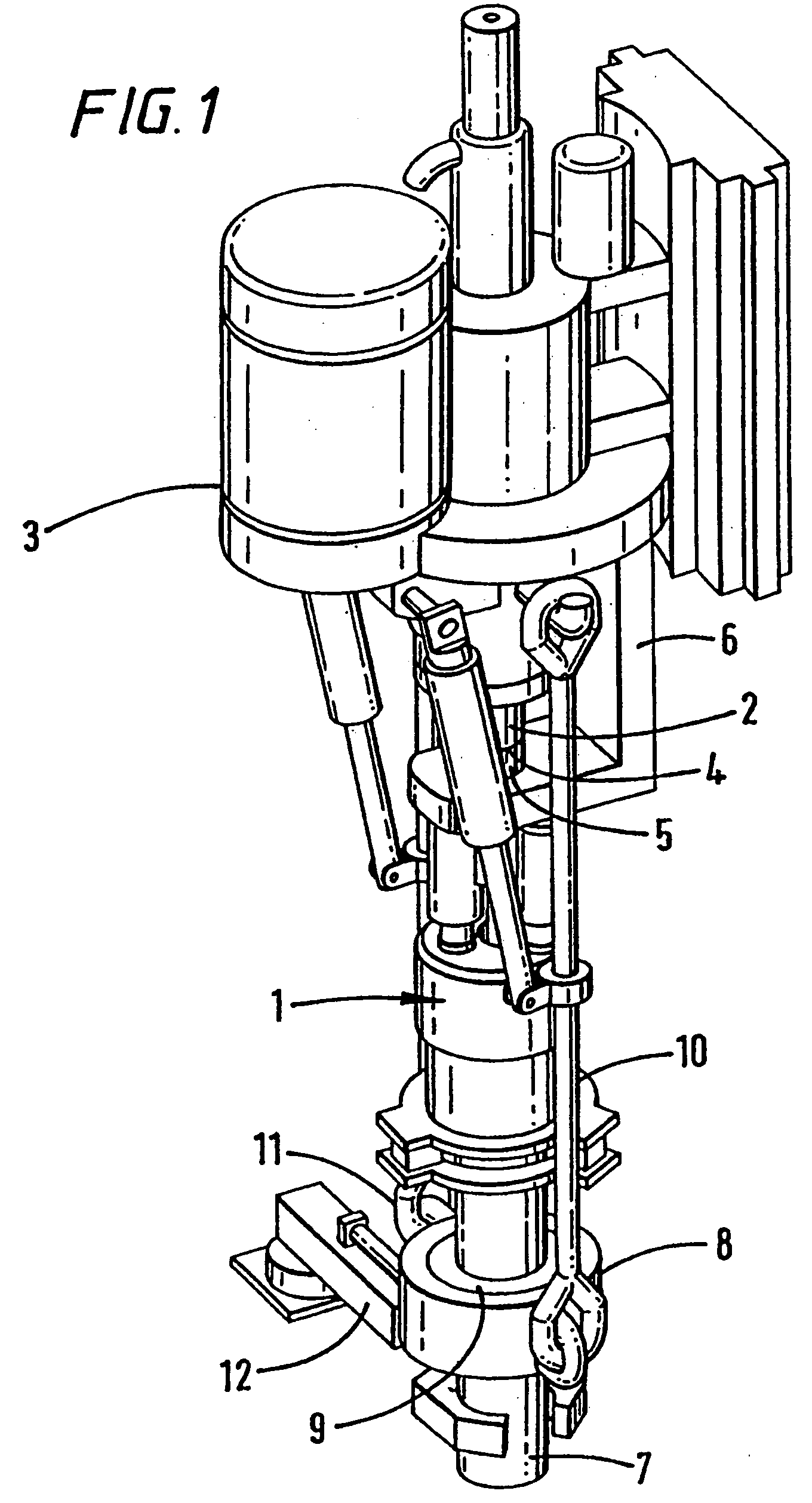
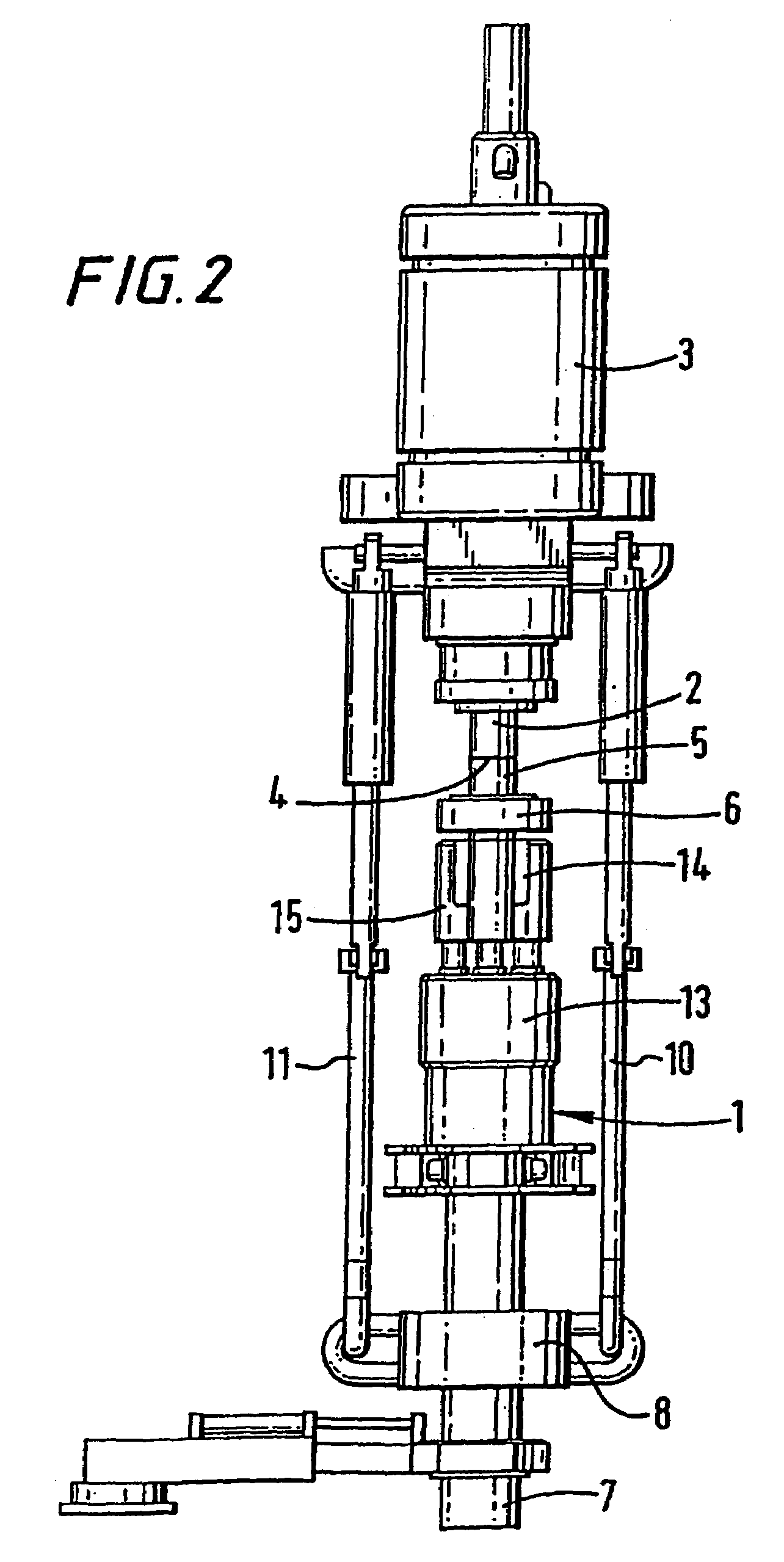
[0016]Referring to the drawings, there is shown an apparatus for facilitating the connection of tubulars using a top drive. The apparatus is generally identified by reference numeral 1.

[0017]The apparatus 1 is shown connected to a rotor 2 of a top drive 3 via connection 4 to a rotor 5 of the apparatus 1. The top drive 3 is located on rails on a derrick of a rig (not shown). A rigid member 6 is fast with a static part of the top drive 3. The rigid member surrounds the rotor 5. The rigid member 6 has a clamp therein which, when required, applies jaws (not shown) to the rotor 5 such that, upon rotation of the rotor 2 of the top drive 3, the apparatus 1 may be connected or disconnected from the top drive 3. When the jaws are released, the rotor 5 may rotate freely within the rigid member6.

[0018]The apparatus 1 is shown with a stand of casing 7 inserted therein. An elevator 8 is shown gripping the stand of casing 7 with the use of gripping elements 9. The elevator 8 is suspended from the...


PUM


Abstract

An apparatus and method for facilitating the connection of tubulars using a top drive and is, more particularly but not exclusively, intended for facilitating the connection of a section or stand of casing to a string of casing.

Description

CROSS-REFERENCE TO RELATED APPLICATIONS[0001]This application is a continuation of co-pending U.S. patent application Ser. No. 09 / 868,790, filed Sep. 4, 2001, now U.S. Pat. No. 6,725,938, which is the National State of International Application No. PCT / GB 99 / 03951, filed on Nov. 29, 1999, and published under PCT Article 21(2) in English, which claims priority of United Kingdom Application Serial No. GB9828673.5, filed on Dec. 24, 1998. The aforementioned applications are herein incorporated by reference in their entirety.BACKGROUND OF THE INVENTION[0002]This invention relates to an apparatus and method for facilitating the connection of tubulars using a top drive and is, more particularly but not exclusively, intended for facilitating the connection of a section or stand of casing to a string of casing.SUMMARY OF THE INVENTION[0003]In the construction of oil or gas wells it is usually necessary to line the borehole with a string of tubulars known as casing. Because of the length of ...

Claims


Application Information

Patent Timeline
IPC IPC(8): E21B19/16E21B21/10
CPCE21B19/16E21B21/106
Inventor PIETRAS, BERND-GEORG
Owner WEATHERFORD TECH HLDG LLC
Why Eureka
Try Eureka