Device for holding a load on a load support of an industrial truck

a technology for industrial trucks and supports, which is applied in the direction of lifting devices, transportation items, other load carrying vehicles, etc., can solve the problems of insufficient fixing of transporting objects, inability to sufficiently clamp transporting objects, and narrow height differences between individual transporting objects, so as to prevent damage to transporting objects, improve safety, and improve the effect of securing

Active Publication Date: 2007-05-08
JUNGHEINRICH AG
View PDF28 Cites 21 Cited by
  • Summary
  • Abstract
  • Description
  • Claims
  • Application Information

AI Technical Summary

Benefits of technology

[0008]In the device according to the invention, a support construction, adjustable in its height, is mounted above the load support on the industrial truck. With the aid of a lifting drive, the support construction can be shifted in its height. Across a plane, which approximately corresponds to the area of a pallet, for instance, it has several vertical guidances, in which plungers are vertically guided. When the plungers are not fastened, they can find support on the respective transporting object which is situated there under. If it is taken care that after this process the plungers remain in this position, a secure fixing of the transporting object is achieved. Therefore this invention further provides a clamping device, by which the plungers can be clamped fast in the guidances on arbitrary height positions. An actuation device provides for optional clamping or releasing of the plungers in the guidances.
[0009]In the invention, a greater number of plungers which are arranged in a field corresponding about to the extension of the load, and which can be lowered onto a load in such a manner that they reproduce the discontinuous surface contour of the load, provides for sufficient securing of the transporting object on the load support. All the plungers are in contact with the load and can be vertically fixed. Through this, securing of the load is provided, particularly against canting over.
[0013]According to a further form of realisation of this invention, the plungers have a stop on the ends, which prevents any slipping of the plungers towards the downside. For instance, enlargements of the plungers on its upper ends can serve for this purpose. The plungers, which are preferably circle-shaped in section, as well as the bores assigned thereto, can be realised as pipes or also in a massive manner.
[0019]According to the invention, a further possibility of control results when second sensors, connected to the controlling device, are provided on the support construction, which emit a second sensor signal when a plunger reaches a maximum lower position. The controlling device stops the lowering movement of the support construction, when all the plungers are lifted with respect to the undermost position. This sensor set-up serves to stop the lowering movement at the earliest moment as is possible. Thus, it serves for time-saving.
[0020]For instance, the sensors can be realised in that electric contacts are provided on the support construction, which co-operate with contact surfaces on the plungers. Preferably, the lower end of the plungers is enlarged, in order to have better securing and to prevent damage of the transporting object. In every case, it is advantageous when the bottom end surfaces of the plungers have a coating or the like with a high frictional value.

Problems solved by technology

When there are several transporting objects of different height on the pallet, or when there are several pallets with transporting objects of different heights on the load support, any sufficient fixing of the transporting object is not possible.
However, it is not possible to sufficiently clamp fast transporting objects of different height which are situated in the fork direction with respect to each other.
It is a disadvantage of this solution that the height differences between the individual transporting objects have to be in narrow limits.

Method used


Image

  • Device for holding a load on a load support of an industrial truck
  • Device for holding a load on a load support of an industrial truck
  • Device for holding a load on a load support of an industrial truck

Examples


Embodiment Construction

[0021]While this invention may be embodied in many different forms, there are described in detail herein a specific preferred embodiment of the invention. This description is an exemplification of the principles of the invention and is not intended to limit the invention to the particular embodiment illustrated

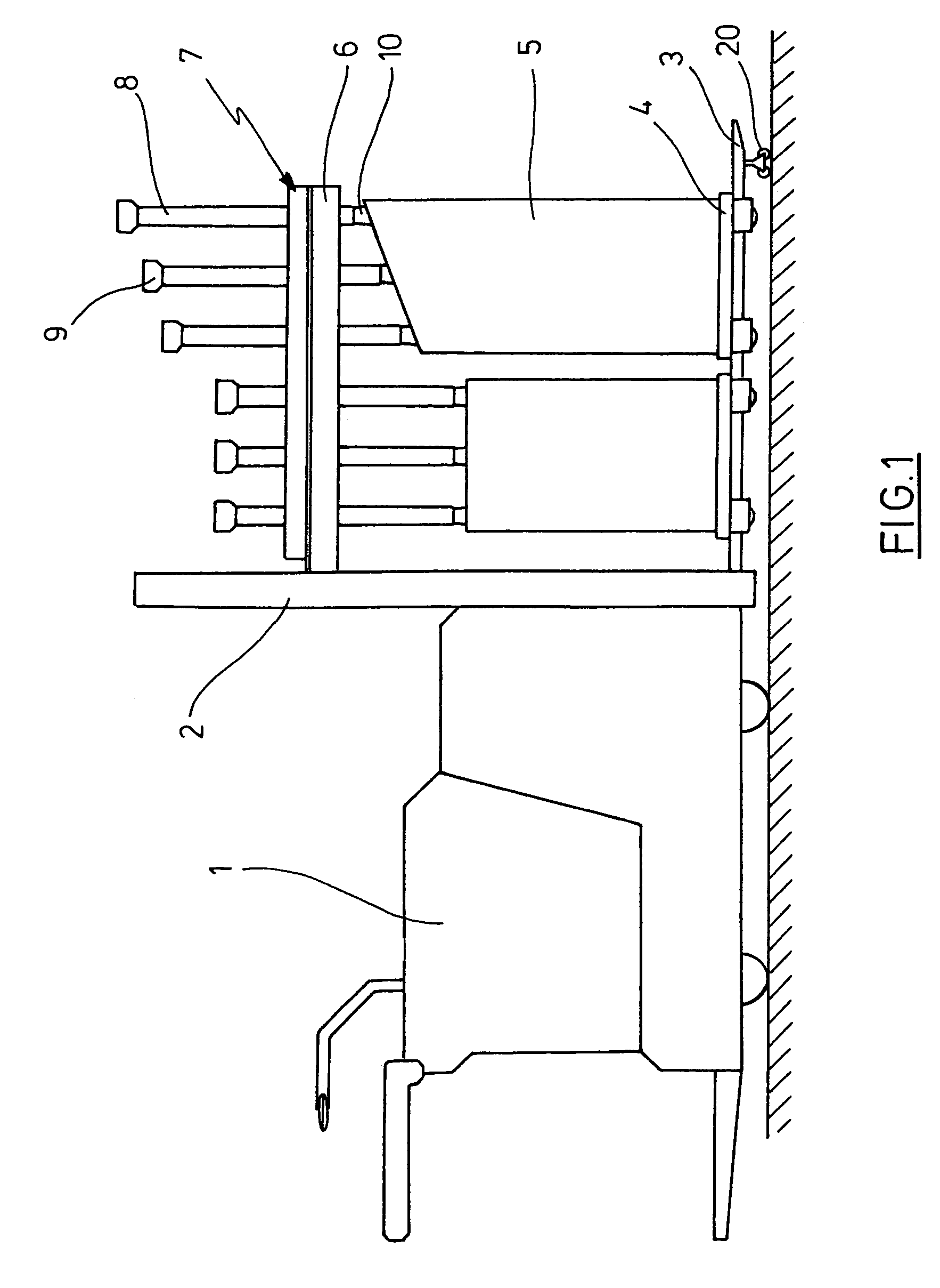
[0022]FIG. 1 shows the side view of an industrial truck with a device according to the invention.

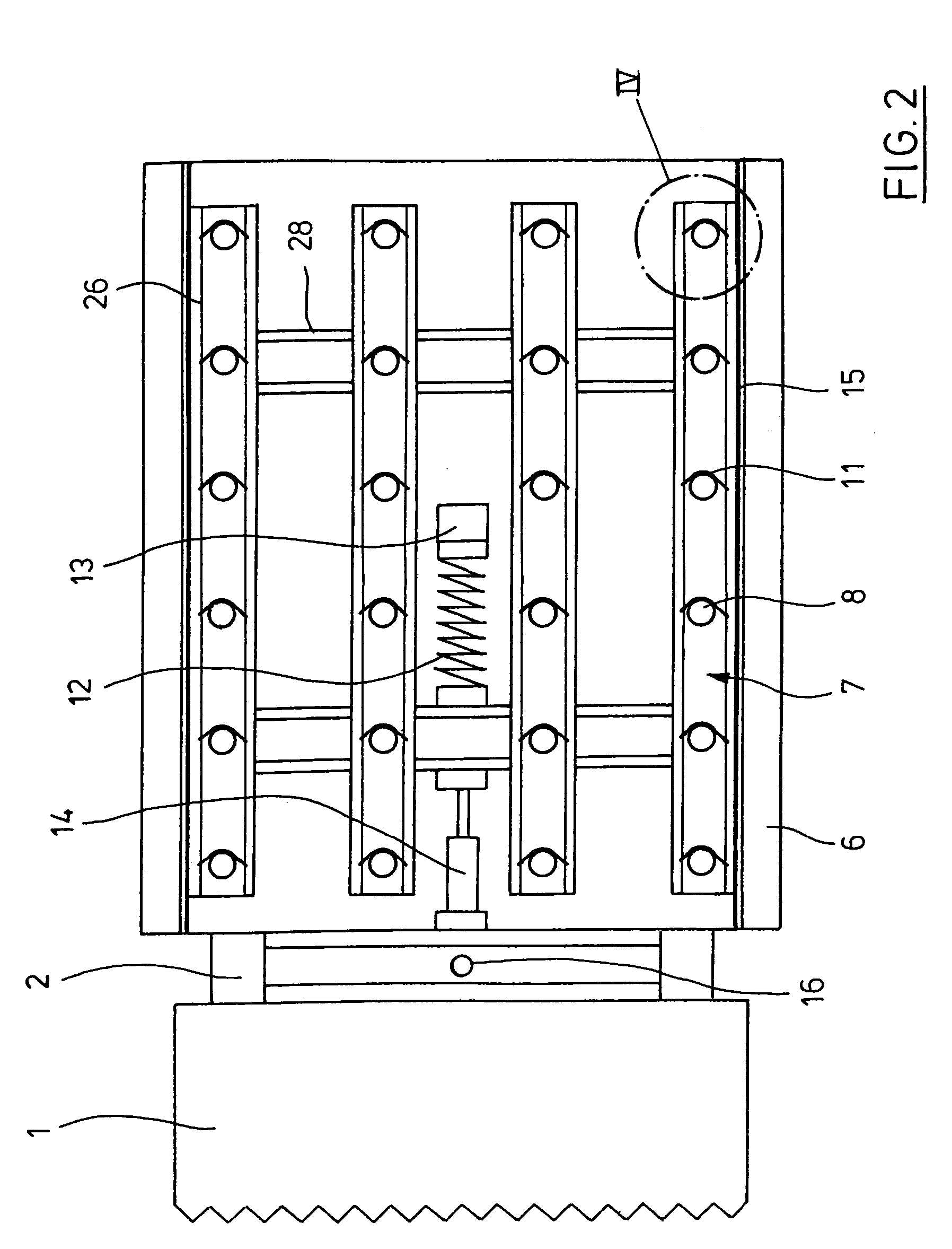
[0023]FIG. 2 shows the top view of the representation after FIG. 1.

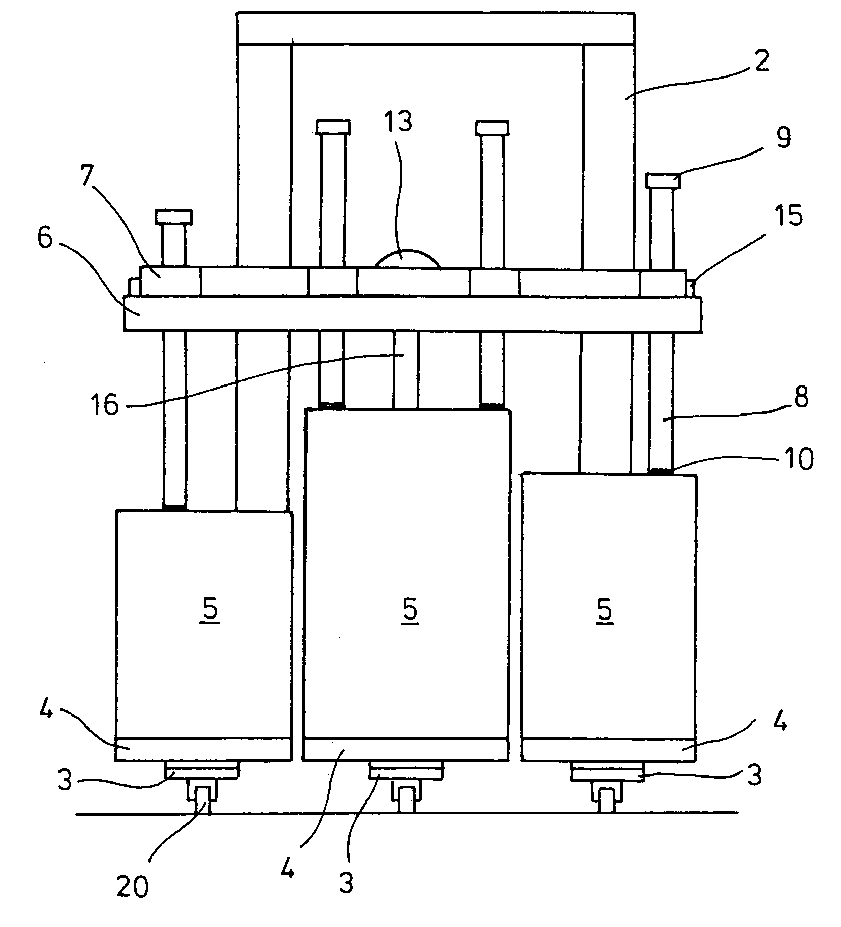
[0024]FIG. 3 shows the front view of the industrial truck after FIG. 1 with the device according to the invention.

[0025]FIG. 4 shows detail 4 in FIG. 2.

[0026]FIG. 5 shows a section through the representation after FIG. 4 along the line 5—5.

[0027]FIG. 6 schematically shows the bottom side of the support plate according to the device of invention.

[0028]In the FIGS. 1 to 3, an electric drawbar lifting truck 1 can be recognised, with a fork support, having three fork tines 3 (see FIG. 3), which are provided with sustain...


PUM


Abstract

Device for holding a load on a load support of an industrial truck with the following characteristics:a support construction, adjustable in its height by a lifting drive, is mounted above the load supportthe support construction has several vertical guidances, distributed across a plane, in each of which one plunger (8) is vertically guideda clamping device is attached on the support construction, by means of which the plungers are fixable in the guidances in an arbitrary height position, andan actuation device for the clamping device for optional clamping or releasing the plungers in their guidances.

Description

CROSS-REFERENCE TO RELATED APPLICATIONS[0001]Not applicable.STATEMENT REGARDING FEDERALLY SPONSORED RESEARCH[0002]Not applicable.BACKGROUND OF THE INVENTION[0003]Fork lifters, shovel loaders or the like industrial trucks have a load support for taking up, transporting and setting down of a load. Mostly, the transporting object is disposed on pallets, which on their part can be transported with the load fork of an industrial truck, e.g.[0004]Transporting objects having a high centre of gravity or a low weight at a small area of standing up may fall down from the pallet or the load support, respectively, particularly when the industrial truck drives over uneven ground or through curves. For this reason, it is known since a long time to use so-called load holders, which exert a push from the upside onto the transporting object, in order to prevent any falling down from the pallet or of the pallet from the load support. From DE 9418354 U1 or EP 467210 B1 a holding device has become know...

Claims


Application Information

Patent Timeline
Patent Type & Authority Patents(United States)
IPC IPC(8): B66F9/12B66F9/18
CPCB66F9/18
Inventor BRUNS, RAINERSTEIGER, STEFANWILLE, JAN-HENNING
Owner JUNGHEINRICH AG
Why Eureka
Try Eureka