Mechanic's creeper

Inactive Publication Date: 2007-05-08
WHITESIDE MFG
View PDF27 Cites 8 Cited by
  • Summary
  • Abstract
  • Description
  • Claims
  • Application Information

AI Technical Summary

Benefits of technology

[0008]It is thus an object of the present invention to provide a mechanic's creeper, wherein an improved wheel design is employed in the casters assemblies so as to decrease friction between the wheels and the ground surface on which the mechanic's creeper is employed.

Problems solved by technology

Because the padding sections provided between the side rails are not normally as wide as the breadth of the shoulders of the typical user, the sharp edges can often present a discomfort to the user.
These protrusions can be an additional source of discomfort to the user because they are likely to snag and tear the user's clothing and scratch the user's body.
The width of the side rails in mechanic's creepers of the prior art relative to the diameter of the caster raceways needed to support the creeper also presents problems.
As such, the portion of the bearing race which extends beyond the side rails is susceptible to being bumped or otherwise contacted, which could readily loosen or otherwise damage the caster assembly.
Moreover, since the bearing race does not fully engage the side rail all the way around the race, the rocking forces born by the caster assemblies as the mechanic's creeper is utilized create weaknesses in the caster assemblies.
For instance, the nuts securing the bolts through the side rails tend to loosen due to the torque placed upon the stem of the bolt as the creeper is moved and the caster assemblies roll and change directions.
Moreover, adverse forces on the caster stems may well cause a shearing of these stems.
In addition, because the bearing races do not completely engage the side rails, the weight placed upon the mechanic's creeper (i.e., the weight of the user's body) is not evenly distributed to the bearing race and the bearings therein.
This increases the wearing of the bearings and therefore shortens the useful life of the caster assemblies and the mechanic's creeper as a whole.
Mechanic's creepers are designed to be capable of moving in any direction and, thus, excessive friction between the caster wheels and the ground surface is counterproductive to the mobility of the mechanic's creeper.

Method used


Image

  • Mechanic's creeper
  • Mechanic's creeper
  • Mechanic's creeper

Examples


Embodiment Construction

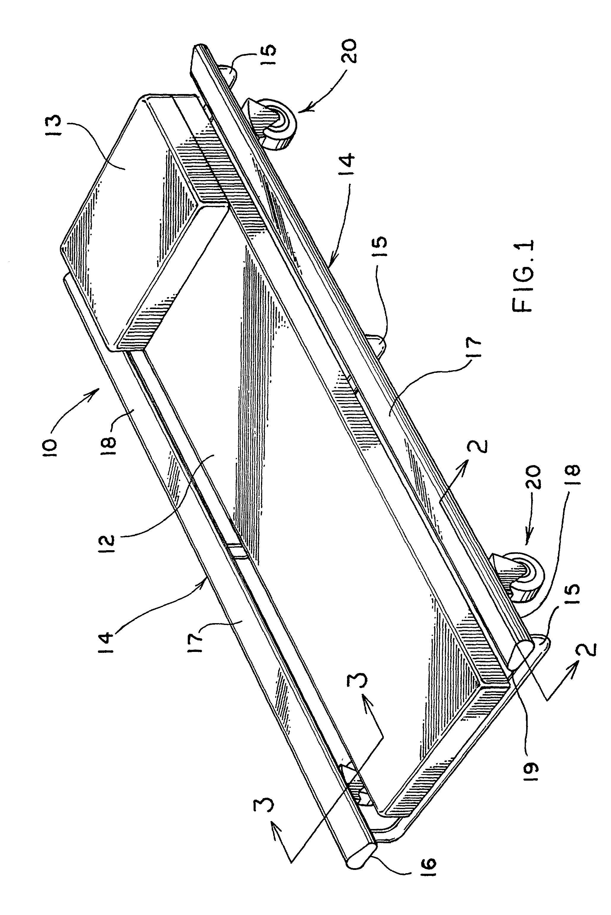
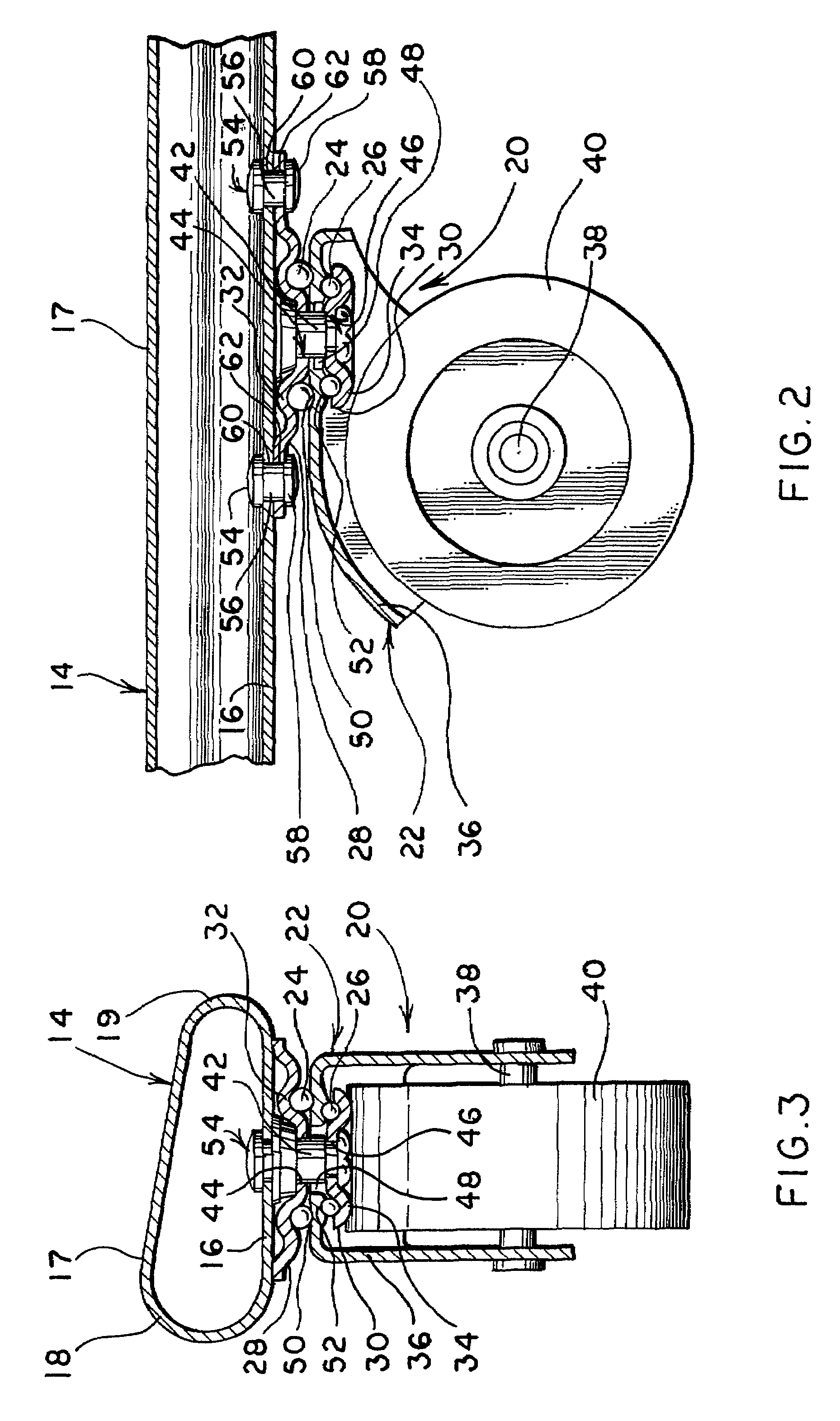
[0023]A mechanic's creeper made in accordance with the concepts of the present invention is generally indicated by the numeral 10 and includes padding 12 and, optionally, a headrest 13 held between opposed side rails, generally indicated by the numeral 14, on a plurality of crossbars 15. As hereinabove discussed, side rails of the prior art are normally of square or rectangular cross section and therefore provide sharp edges adjacent to the padding held between the side rails. However, as seen in FIGS. 1 and 3, side rails 14 of the present invention are generally tear-shaped so as to eliminate the discomfort encountered when utilizing mechanic's creepers of the prior art. As such, each side rail 14 is hollow and includes a generally horizontal bottom surface 16, which thus lies substantially parallel to the surface upon which creeper 10 is placed, and an opposed top surface 17 which is angled in relation to bottom surface 16 so as to provide a generally tapered cross section. The la...


PUM


Abstract

A mechanic's creeper (10) includes a pad (12) supported between a plurality of side rails (14) by a plurality of crossbars (15). The side rails (14) are of tear-shaped cross section such that no sharp edges are provided adjacent to the pad (12) held between the side rails (14). The pad (12), side rails (14), and crossbars (15) are held off the ground by a plurality of caster assemblies (20). The caster assemblies (20) are connected only to the bottom surface (16) of the side rails (14) such that no protrusion is created on the top surface (17) of the side rails (14). Specifically, each of the caster assemblies (20) is connected to an associated side rail (14) by a rivet nut (54) that communicates only with the bottom surface (16) of side rail (14). The caster assemblies (20) further include rolling elements (24, 26) and bearing races (32, 34) that allow the caster assemblies (20) to rotate about the axis of a kingpin (42). The kingpin (42) retains the various elements of the caster assemblies (20) in an operative relation. Additionally, the lateral extent of side rails (14) is such that the top race (32) lies wholly within the vertical profile of its associated side rail (14). An improved wheel design for a caster assembly is also provided, wherein the wheel (140) provides a rounded radial surface (160) to lessen the amount of surface area contact between the radial surface (160) and the surface upon which the wheel (140) rests.

Description

CROSS REFERENCE TO RELATED APPLICATION[0001]This application is a continuation in part of U.S. patent application Ser. No. 09 / 523,469, filed Mar. 10, 2000.TECHNICAL FIELD[0002]The present invention relates to mechanic's creepers and, more particularly, to a mechanic's creeper having an improved mobility based on a unique design of the wheels. Moreover, this invention relates to a creeper with an improved side rail and caster assembly. These design features serve to provide a more contoured fit for the user, an improved resistance to wear and tear of the caster assemblies, a lack of protrusions on the side rails so as to avoid the snagging and tearing of clothes and possible scratches to the user's body.BACKGROUND ART[0003]Mechanic's creepers are in wide-spread use, however, it has been found that the common, prior art mechanic's creeper design can be improved in a number of ways. Currently, mechanic's creepers are designed with side rails usually of rectangular or square cross secti...

Claims


Application Information

Patent Timeline
IPC IPC(8): B25H5/00B60B33/00
CPCB25H5/00B60B3/001B60B3/02B60B5/02B60B33/0002B60B33/0005B60B33/0028B60B33/0039B60B33/0049B60B33/0057B60B33/0068B60B33/0073B60B33/0018Y10T16/184
Inventor WHITESIDE, KIRT E.
Owner WHITESIDE MFG
Why Eureka
Try Eureka