Surgical scalpel

Inactive Publication Date: 2007-04-10
MASURY DAVID H +1
View PDF26 Cites 10 Cited by
  • Summary
  • Abstract
  • Description
  • Claims
  • Application Information

AI Technical Summary

Benefits of technology

[0006]When assembled, with the two halves ultrasonically welded together, the molded plastic housing has an upper and a lower radiused edge, and interior and exterior wall surfaces. In preferred embodiments, the interior walls of the molded plastic housing are ribbed, with the innermost surfaces of the ribs defining a channel for the slidable engagement of a blade carrier. The use of molded ribs, rather than simply employing an unribbed inner wall surface, offers well known advantages in the injection molding process. In addition, the ribbed bearing surface provides decreased friction in blade carrier movement when compared to the frictional forces encountered with a non-ribbed bearing surface. Other features of the channel include, an open end through which a surgical blade is extended during use, a slot through the lower radiused edge for slidable engagement of an actuator / locking fin, a single-use indicator window, and a retaining element for engaging a distal end of a leaf spring.

Problems solved by technology

When working with such a sharp instrument, there is always a danger to medical personnel of inadvertent puncture of the skin.

Method used


Image

  • Surgical scalpel
  • Surgical scalpel
  • Surgical scalpel

Examples


Embodiment Construction

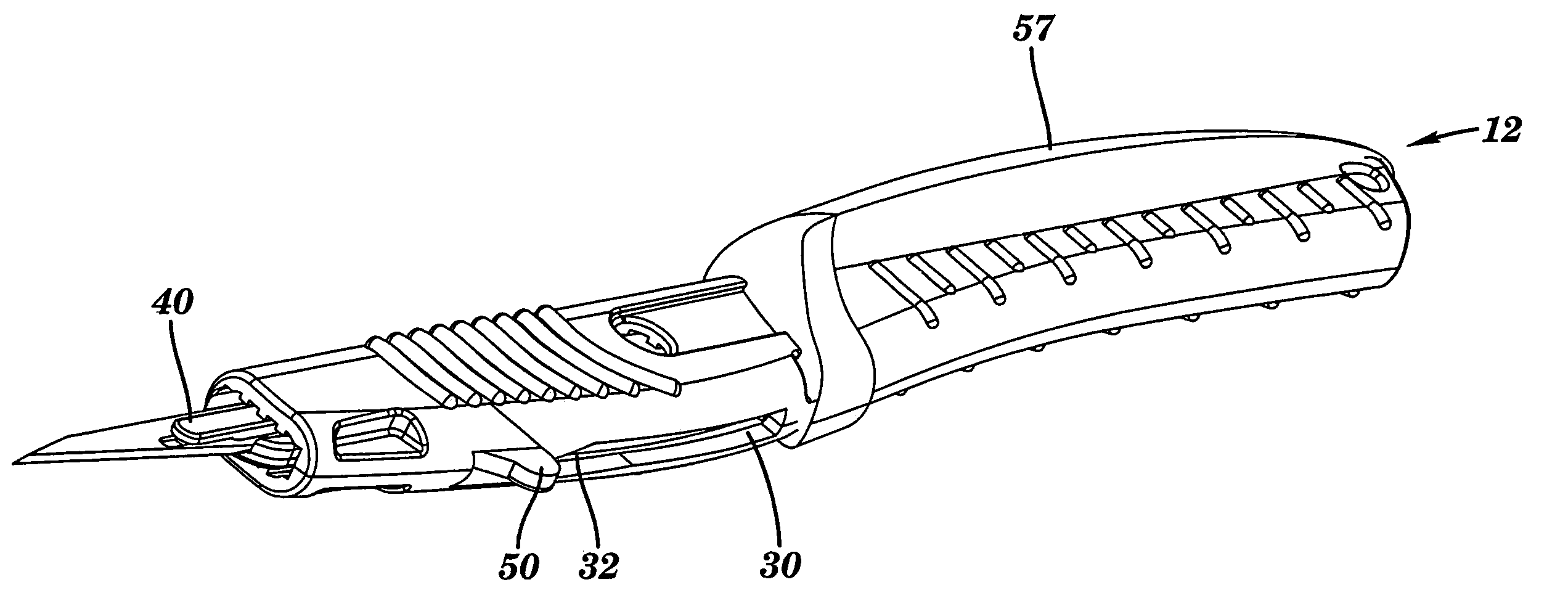
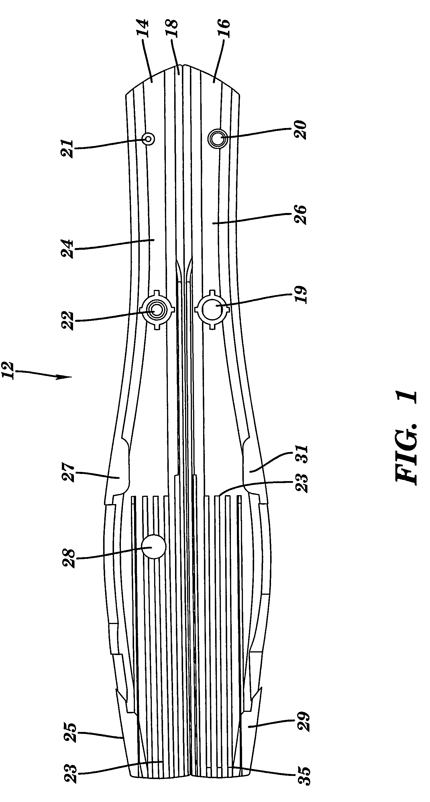
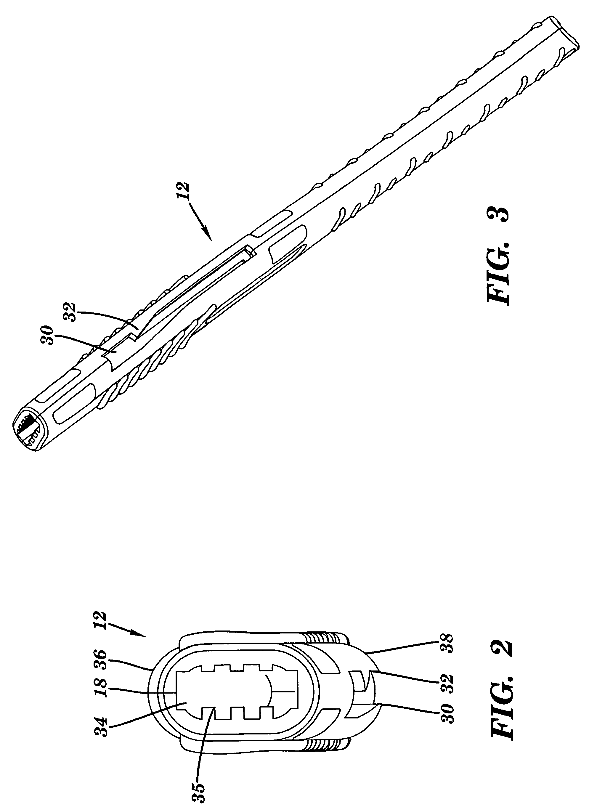
[0018]Referring to FIG. 1, an element of the device of the present invention is shown in plan view. More specifically, FIG. 1 depicts a molded plastic housing (12). The housing consists of a first half (14), and a second half (16), which are mated in the assembled device. While the first half (14) and the second half (16) can be independently molded prior to assembly, in preferred embodiments, the two halves are molded as a single unit and joined by a live hinge (18) which runs longitudinally and defines a common edge of each half. The live hinge (18) is essentially a thinly molded plastic strip which holds the two halves together and, by virtue of its thinness, enables the two halves to mate without breaking the hinge. Also shown in FIG. 1 is a molded press fit with male (21) and female (20) elements designed to hold the mated halves (14 and 16) together in the assembled device prior to ultrasonic welding. Ultrasonic welding flanges (25, 27, 29 and 31) are provided to effectively a...


PUM


Abstract

Disclosed is a single-use surgical scalpel having two molded plastic elements, and a surgical blade. The first molded plastic element is a housing. The housing has an upper and a lower radiused edge, and ribbed interior wall surfaces. The ribbed interior wall surfaces of the molded plastic housing define a channel for slidable engagement of the second molded plastic element which is referred to as a blade carrier. The channel has one open end through which a surgical blade is extended during use, a slot through the lower radiused edge for slidable engagement of an actuator / locking fin, a single-use indicator window, and a retaining element for engaging a distal end of a leaf spring. The molded plastic blade carrier has a first end adapted for engaging the surgical blade, a second end having a leaf spring to assist in blade retraction, the leaf spring having a proximal and a distal end, and a central portion having the actuator / locking fin and a single-use indicator. A single-mold embodiment is also disclosed.

Description

CROSS REFERENCE TO RELATED APPLICATIONS[0001]This application is a Continuation of Application No. 10 / 075,170, filed Feb. 14, 2002 now U.S. Pat. No. 6,645,216.BACKGROUND OF THE INVENTION[0002]Surgical scalpels are used by medical personnel in connection with surgical procedures ranging from simple outpatient procedures to extraordinarily complex procedures carried out under general anesthesia. When working with such a sharp instrument, there is always a danger to medical personnel of inadvertent puncture of the skin. Aside from the injury itself, the more important concern for the punctured individual relates to the potential spread of disease from a non-sterile instrument.[0003]The use of surgical scalpels having a retractable blade has been suggested as a means for reducing the number of such puncture wounds. Indeed, a number of patents have been issued which are directed toward surgical scalpels having retractable blades. These include, for example, U.S. Pat. Nos. 5,531,754, 6,25...

Claims


Application Information

Patent Timeline
IPC IPC(8): A61B17/32A61B19/00
CPCA61B17/3211A61B2017/32113A61B2019/4873A61B2090/0814
Inventor MASURY, DAVID H.THOMPSON, EDWARD P.
Owner MASURY DAVID H
Why Eureka
Try Eureka