Segmental floating bulkhead assembly

a floating bulkhead and segment technology, applied in the field of floating bulkhead assemblies, can solve the problems of increased manufacturing costs, difficult maneuverability and operation, and high maintenance costs, and achieve the effect of increasing the buoyancy of the bulkhead assembly

Inactive Publication Date: 2007-05-08
AUBIAN ENG
View PDF8 Cites 11 Cited by
  • Summary
  • Abstract
  • Description
  • Claims
  • Application Information

AI Technical Summary

Benefits of technology

[0012]Another embodiment of the present invention includes a bulkhead assembly for dry isolation of a water passage of a dam. The bulkhead assembly comprises a plurality of floatable caisson members bound together to form a platform assembly adapted to float in a horizontal attitude on a water body surface. At least one of the caisson members includes at least two HSS steel tubes connected in parallel with a side plate, the HSS tubes and the side plate defining at least one intermediate space. The at least two tubes are sealed with tube end plates to form at least two sealed chambers, and at least a portion of the at least one intermediate space is sealed to create at least another sealed chamber, with at least one of the sealed chambers including at least one sealable aperture to selectively flood the sealed chamber and to evacuate water from the sealed chamber to cause the bulkhead selectively to move between the horizontal attitude and a vertical attitude in the water body, and selectively to reduce and increase buoyancy of the bulkhead assembly. At least one of the floatable caisson members includes a sealable conduit for selectively permitting flow of water from the water body through the bulkhead assembly.

Problems solved by technology

However, they are difficult to maneuver and operate, more costly to fabricate than conventional bulkhead assemblies, and expensive to maintain.
If not maintained, floating bulkhead assemblies may be deemed unsafe to operate due to unknown conditions in the sealed chambers, internal steel corrosion or unreliable components.
The Ayres Design, which utilizes wide flange steel beams, has several drawbacks compared to the use of hollow rectangular section steel tubes made from flat sheet.
Fabrication using wide flange beams to create a workable caisson requires a great amount of skillful cutting and welding of the beams, which increases the cost of fabrication.
Wide flange beams are not produced in many useable varieties or dimensions, and heavy customization is often required.
This lack of variety also lessens the engineering options.
With wide flange beams, the bottom chamber is generally required to be the sealable chamber of the caisson, which in turn, dictates or limits the engineering options for the size of the caisson.
Bakken and Vonasek reference the drawbacks with the use of rolled rectangular tube sections as being quite heavy and, due to the limited depths available in rolled steel tubes, the anticipated deflections of the units at the bottom of the wall would be excessive and could potentially cause problems with the bottom seal.
Also, a drawback of using large dimension tube sections, for instance, tube sections greater than approximately 0.7 meters wide, is the excess weight and cost.

Method used


Image

  • Segmental floating bulkhead assembly
  • Segmental floating bulkhead assembly
  • Segmental floating bulkhead assembly

Examples


Embodiment Construction

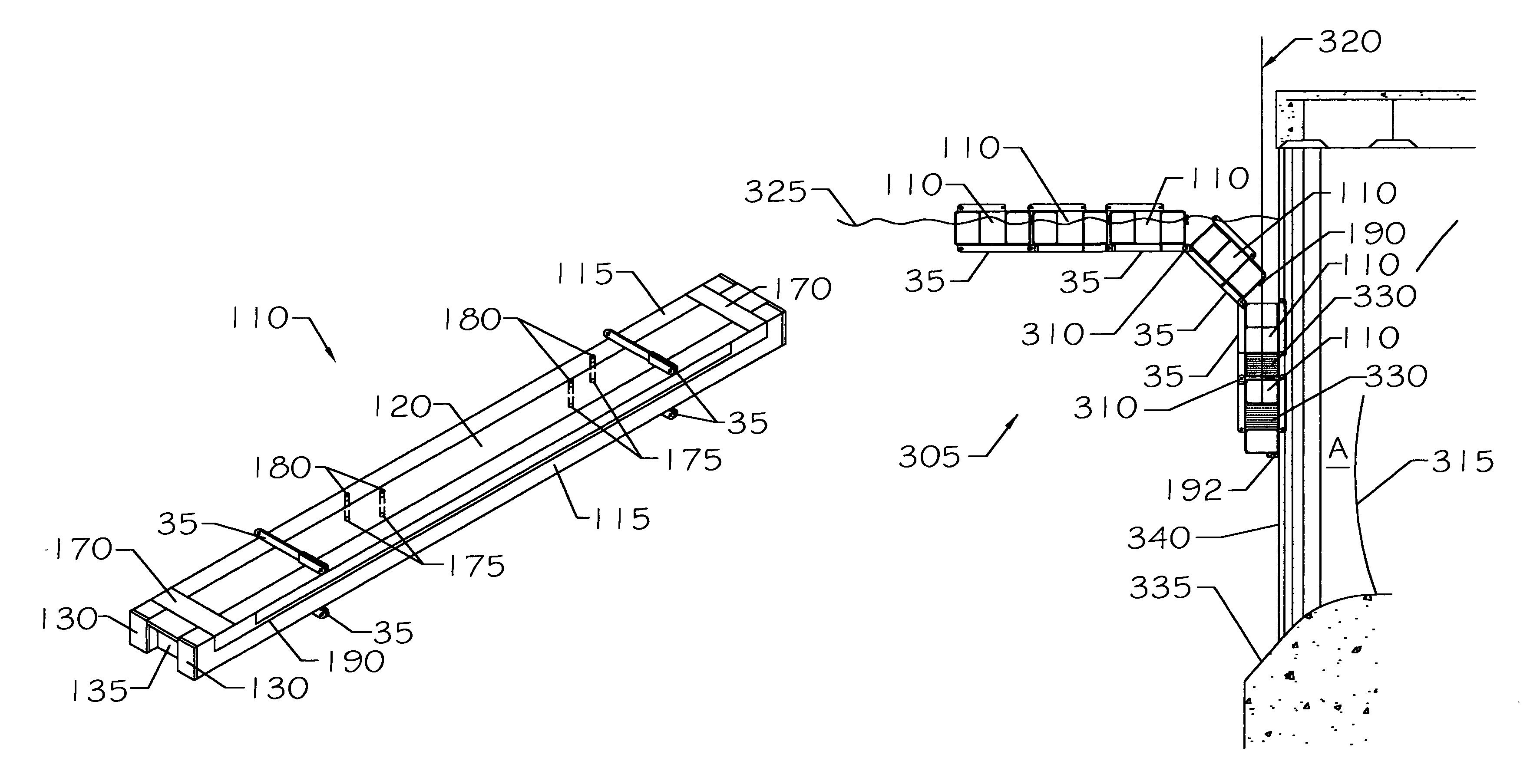
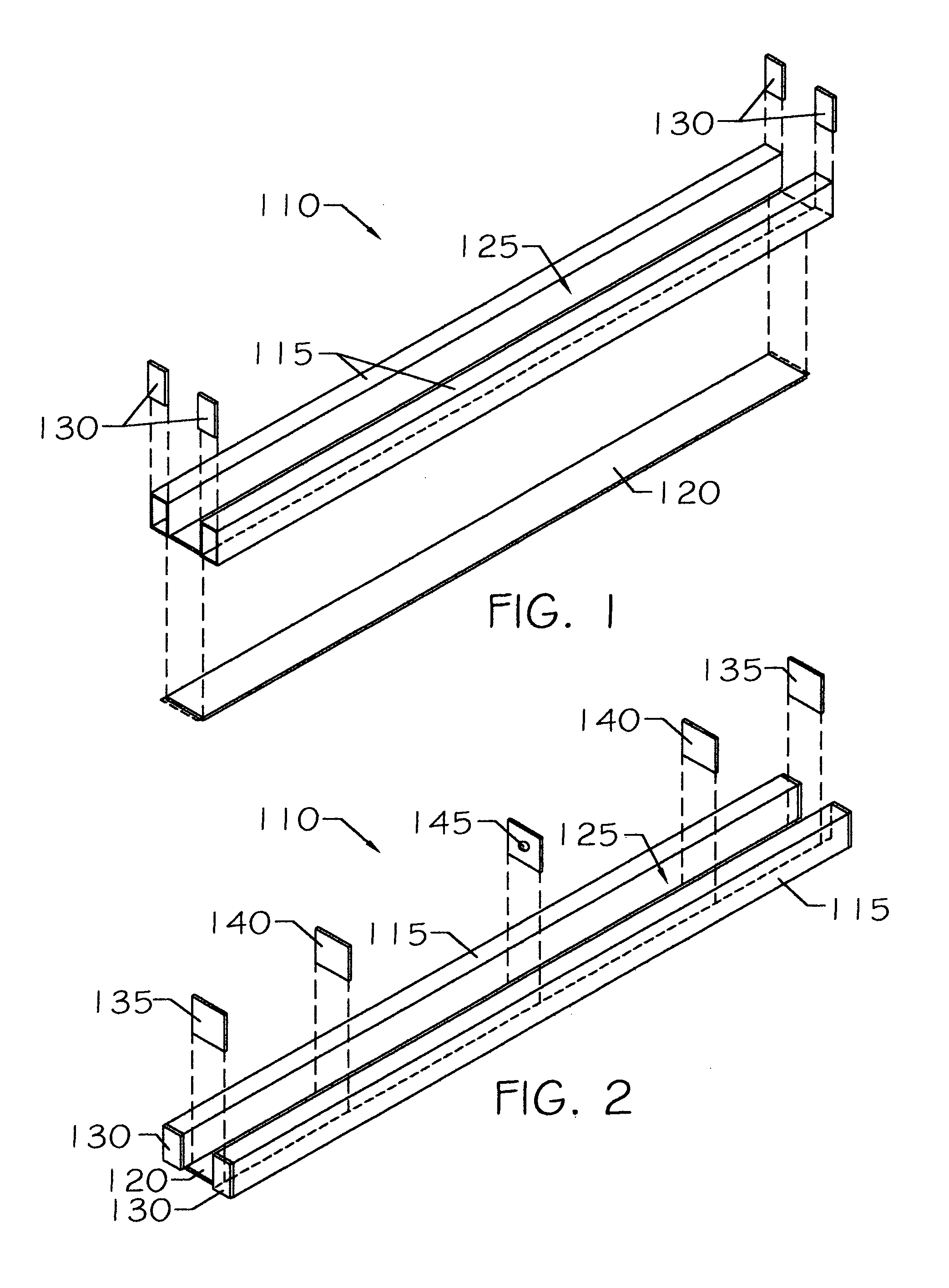
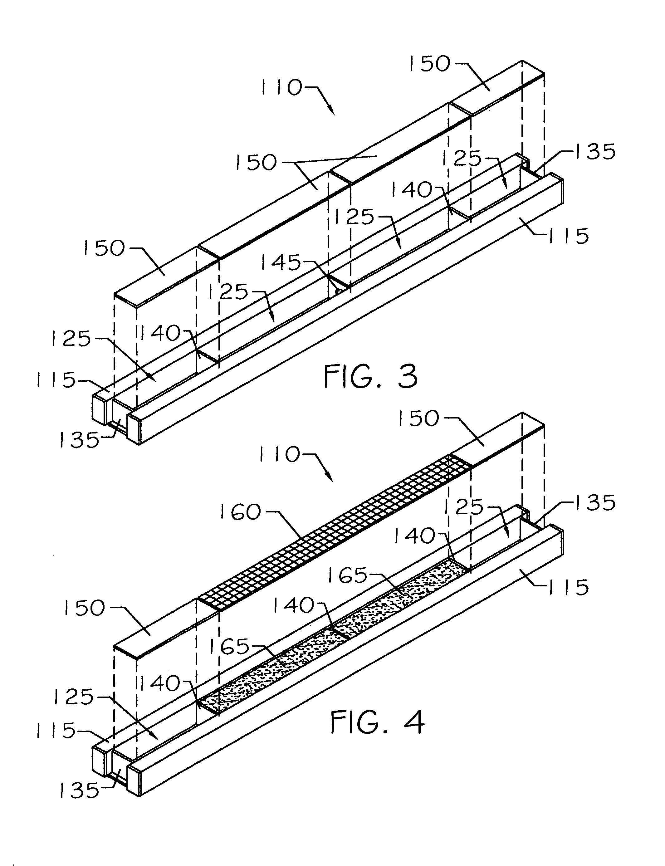
[0032]The present invention is directed to a floatable caisson member for use with a bulkhead assembly for dry isolation of water passages of a dam. In one embodiment of the invention, the floatable caisson member includes at least two hollow, rectangular section, HSS steel tubes made from flat sheet steel, each tube sealed at each end by a tube end plate to form at least two sealed chambers. A side plate is secured to the at least two steel tubes, with the at least two steel tubes and the side plate defining at least one intermediate space. At least one pair of intermediate space end plates is secured between adjacent tubes of the at least two tubes. At least one intermediate chamber plate is secured to the at least two steel tubes opposite the side plate. The intermediate chamber plate seals at least a portion of the at least one intermediate space to create at least another sealed chamber. At least one sealed chamber includes at least one sealable aperture to selectively flood th...


PUM


Abstract

The present invention is directed to the structure of a floatable caisson member and to a segmental floatable bulkhead assembly, formed by assembling a plurality of the floatable caisson members. The present invention also includes a method of fabrication of the floatable caisson member. A segmental floatable bulkhead assembly, formed by assembling a plurality of the floatable caisson members, is employed for dewatering a water passage of a dam.

Description

BACKGROUND OF THE INVENTION[0001]1. Field of the Invention[0002]The present invention relates generally to a bulkhead assembly for dewatering water passages of dams and, more particularly, to a floating bulkhead assembly and, most particularly, to a segmental floating bulkhead assembly for this purpose.[0003]2. Background Information[0004]The standard means for dewatering dam intakes and outlets, such as spillways, outlet works, penstocks and draft tubes, has been with bulkhead assemblies or stop logs placed in opposing slots set in the passageway walls. A bulkhead assembly is a one-piece fabrication that is positioned across the water passage opening in slots to allow the water passage to be dewatered without having to lower the reservoir. The bulkhead assembly is usually lowered into place from the top of the dam with a mobile crane, gantry crane or permanent hoist. For large openings, where a one-piece bulkhead assembly is impractical, a series of horizontal bulkhead assemblies, ...

Claims


Application Information

Patent Timeline
Patent Type & Authority Patents(United States)
IPC IPC(8): E02B7/26
CPCE02B7/16E02B8/04
Inventor LUX, III, FREDERICK
Owner AUBIAN ENG
Why Eureka
Try Eureka