Electrical signal cable

a signal cable and electric technology, applied in the direction of cables, insulated conductors, conductors, etc., can solve the problems of degrading the original signal, air is one of the most difficult elements to incorporate in the design of electrical cables, and twisted pair configurations which incorporate continuous air channels suffer from several major limitations, so as to achieve minimal susceptibility to skin effects and minimal signal degradation

Inactive Publication Date: 2007-05-08
LEYENDECKER ROBERT R
View PDF15 Cites 32 Cited by
  • Summary
  • Abstract
  • Description
  • Claims
  • Application Information

AI Technical Summary

Benefits of technology

[0012]The present invention provides an electrical cable with minimal values of resistance, capacitance and inductance. In addition, the present invention provides an economical means for incorporating air as a dielectric element in electrical cables. The present invention also provides an electrical cable with minimal susceptibility to skin effect. Furthermore, the present invention allows the transmission of low and high power electrical signals with minimal signal degradation.

Problems solved by technology

One or more of these three properties can cause degradation of the original signal as it is transferred through the cable.
It remains a great challenge in the electrical cable industry to minimize and / or carefully control each of these properties over a broad range of frequencies.
Air is also one of the most difficult elements to incorporate in an electrical cable design.
The twisted pair configurations which incorporate a continuous air channel suffer from several major limitations.
In addition, these techniques require relatively complex and expensive manufacturing methods.
Other known methods of providing substantially solid insulating strips between conductors do not incorporate any method for providing air as a substantial dielectric element.
Moreover, these strip and air cavity dielectric techniques do not incorporate a specific means for reducing skin effect.
Previously mentioned Litz wire designs intended to minimize skin effect do not address a specific means for incorporating air to reduce the capacitive effects between the signal source and return conductors of an electrical cable.

Method used


Image

  • Electrical signal cable
  • Electrical signal cable
  • Electrical signal cable

Examples


Embodiment Construction

[0026]While the making and using of various embodiments of the present invention are discussed in detail below, it should be appreciated that the present invention provides many applicable inventive concepts that can be embodied in a wide variety of specific contexts. The specific embodiments discussed herein are merely illustrative of specific ways to make and use the invention and do not delimit the scope of the invention. The discussion herein relates primarily to an electrical signal cable, but it will be understood that the concepts of the present invention are applicable to any electrical signal medium where it is desirable to reduce resistance, capacitance and inductance.

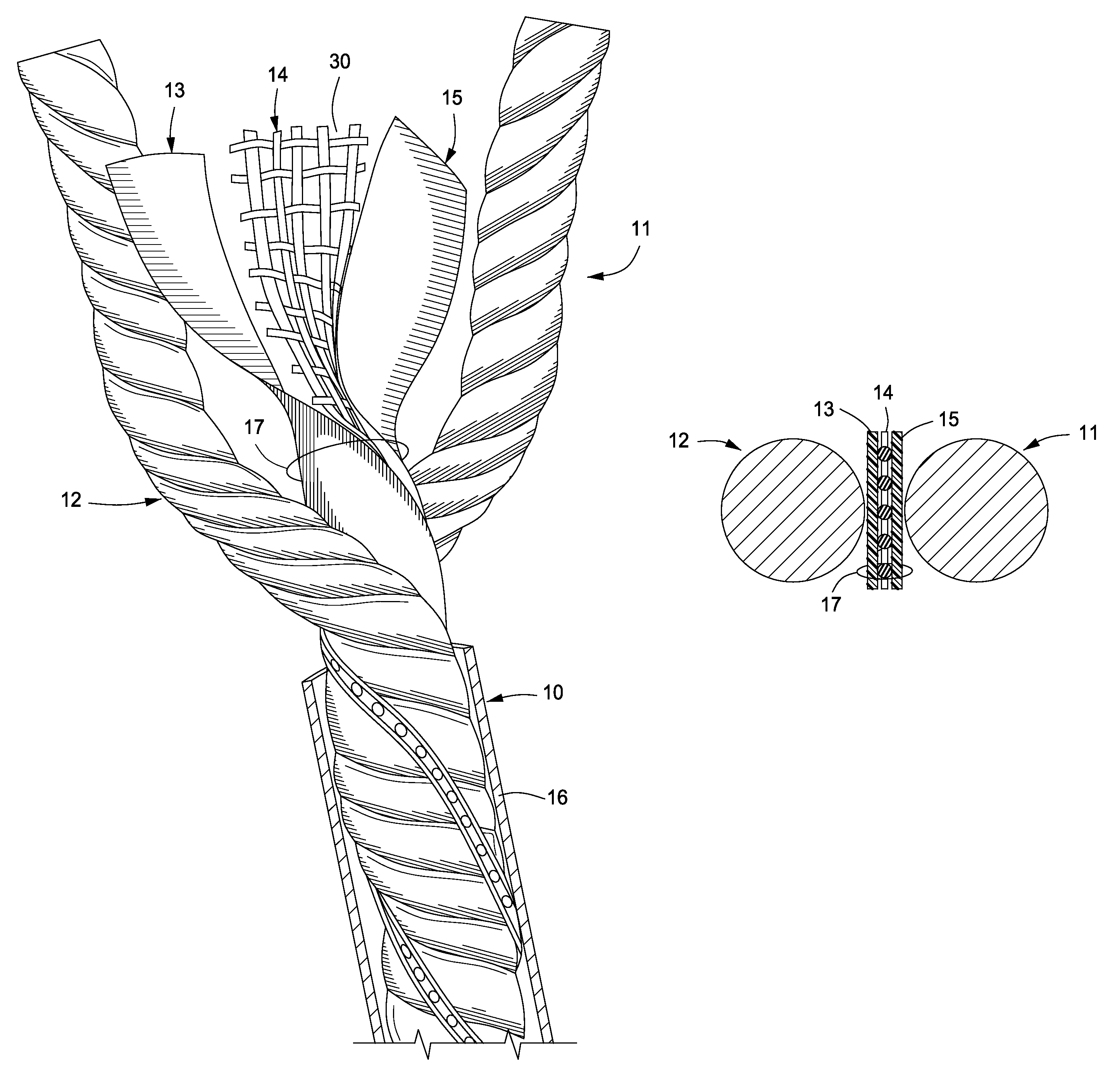
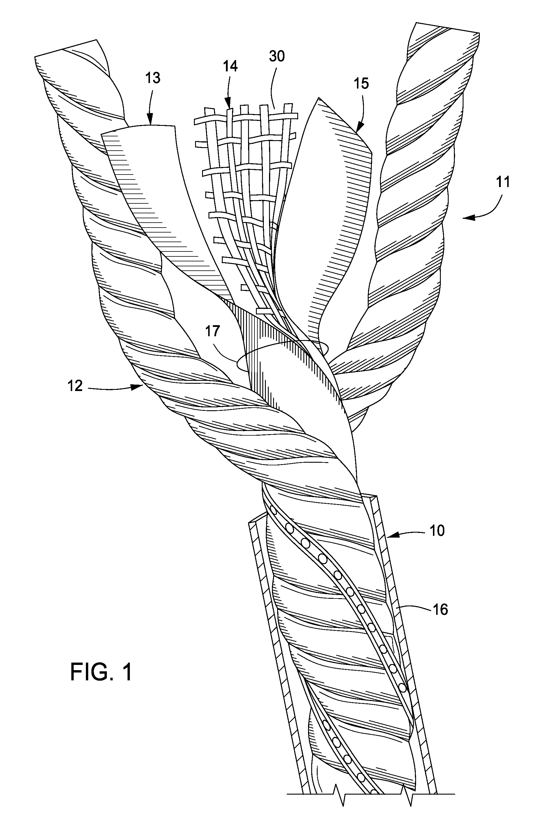
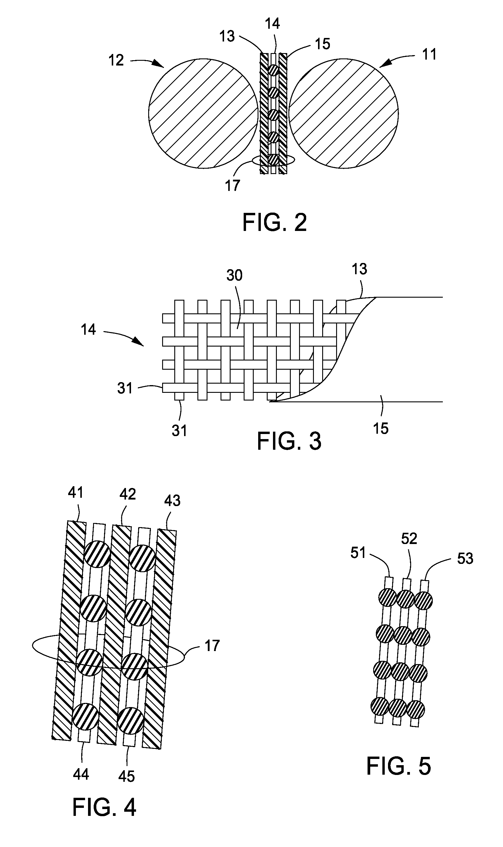
[0027]The present invention provides an electrical cable with minimal values of resistance, capacitance and inductance. In addition, the present invention provides an economical means for incorporating air as a dielectric element in electrical cables. The present invention also provides an electrical cable wi...


PUM

PropertyMeasurementUnit
electrical cableaaaaaaaaaa
flexibleaaaaaaaaaa
lengthaaaaaaaaaa

Abstract

The present invention provides an electrical cable having two or more conductors, one or more multistrip insulators separating the two or more conductors from one another, and a protective cover formed around the two or more conductors and one or more multistrip insulators. The multistrip insulator may include one or more dielectric strips, one or more protective strips or a combination thereof. The present invention also provides a method for manufacturing an electrical cable by providing two or more conductors, separating the two or more conductors from one another using one or more multistrip insulators, and forming a protective cover around the two or more conductors and one or more multistrip insulators.

Description

PRIORITY CLAIM[0001]This patent application is a non-provisional application of U.S. provisional patent application No. 60 / 674,514 filed on Apr. 25, 2005 and entitled “Conductors Insulated by Layers of Dielectric Material,” which is hereby incorporated by reference in its entirety.FIELD OF THE INVENTION[0002]The present invention relates generally to the field of electrical cables and, more particularly, to electrical cables that transmit analog and / or digital signals.BACKGROUND OF THE INVENTION[0003]Electrical cables used to transfer audio, data and radio frequency signals are characterized by capacitive, inductive and resistive properties. Collectively, these properties establish the impedance of the electrical cable. One or more of these three properties can cause degradation of the original signal as it is transferred through the cable. It remains a great challenge in the electrical cable industry to minimize and / or carefully control each of these properties over a broad range o...

Claims


Application Information

Patent Timeline
Patent Type & Authority Patents(United States)
IPC IPC(8): H01B7/00
CPCH01B11/002H01B11/06
Inventor LEYENDECKER, ROBERT R.
Owner LEYENDECKER ROBERT R
Why Eureka
Try Eureka