Circuit interrupting device with a turnbuckle and weld break assembly

a technology of turnbuckle and weld break assembly, which is applied in the direction of circuit-breaking switches, switch power arrangements, contact mechanisms, etc., and can solve problems such as undesirable arcing

Inactive Publication Date: 2007-05-08
HUBBELL INC
View PDF15 Cites 13 Cited by
  • Summary
  • Abstract
  • Description
  • Claims
  • Application Information

AI Technical Summary

Benefits of technology

[0008]Another object of the present invention is to provide a circuit interrupting device that can break welds between contacts in the circuit interrupting device.
[0009]A further object of the present invention is to provide a circuit interrupting device that compensates for erosion of the contacts that occurs during operation.
[0010]These objects are basically attained by a circuit interrupting device that has a circuit interrupter with a stationary contact and a moveable contact. The movable contact is actuated by a solenoid assembly and is movable between a closed position and an open position. In the closed position, the contacts abut one another and allow current to pass through the circuit interrupter. In the open position, the contacts are separated by a gap, preventing current from passing through the circuit interrupter. The movable contact is connected to a plunger of the solenoid assembly by a turnbuckle and weld break assembly. The turnbuckle and weld break assembly functions as a turnbuckle and thereby provides the ability to adjust the wipe distance of the contacts. The turnbuckle and weld break assembly also generates a hammer force to break any welds between the contacts.

Problems solved by technology

Arcing is undesirable because it causes erosion of the contacts.

Method used


Image

  • Circuit interrupting device with a turnbuckle and weld break assembly
  • Circuit interrupting device with a turnbuckle and weld break assembly
  • Circuit interrupting device with a turnbuckle and weld break assembly

Examples


Embodiment Construction

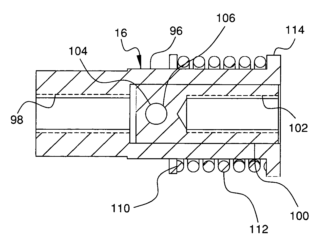
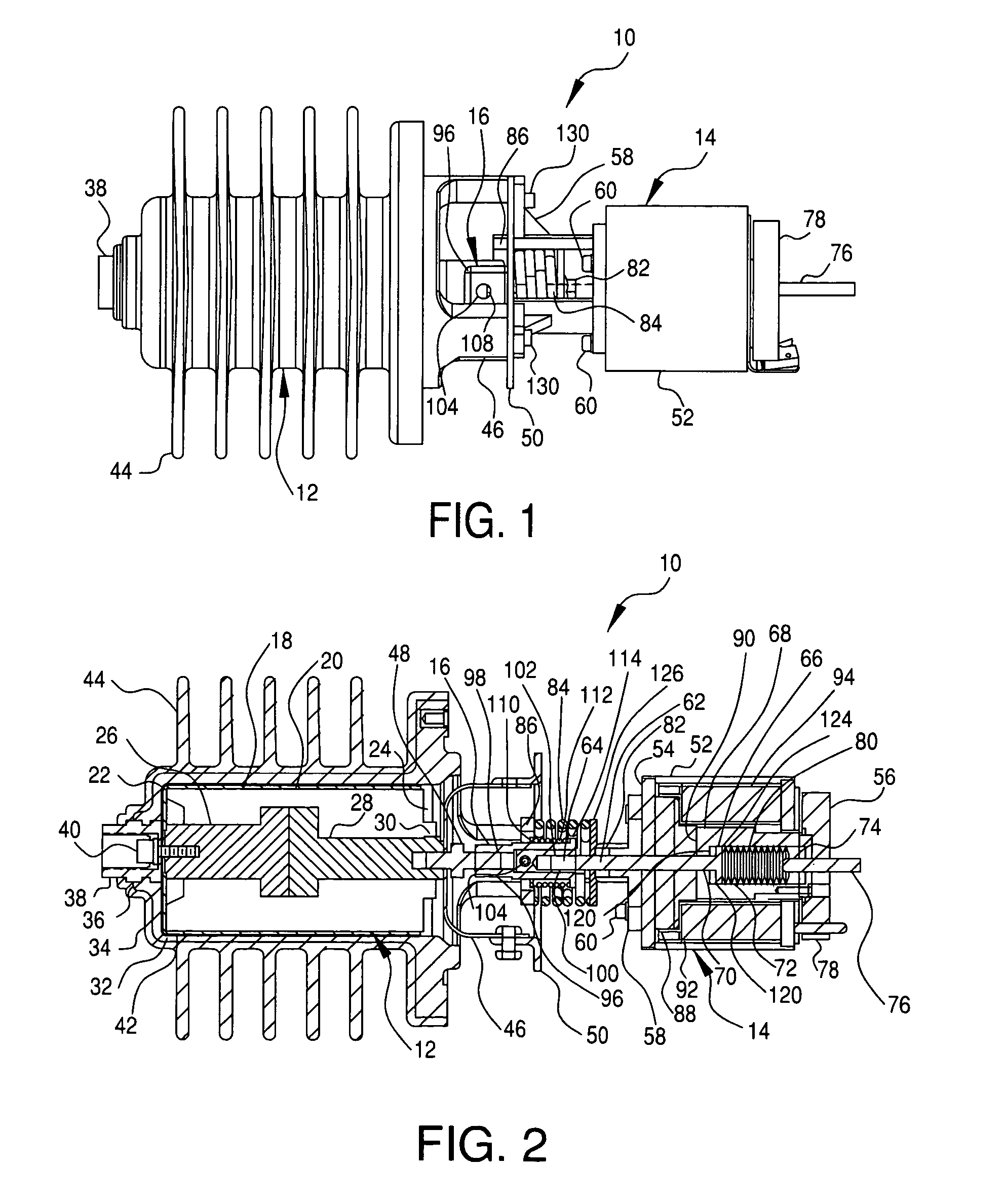
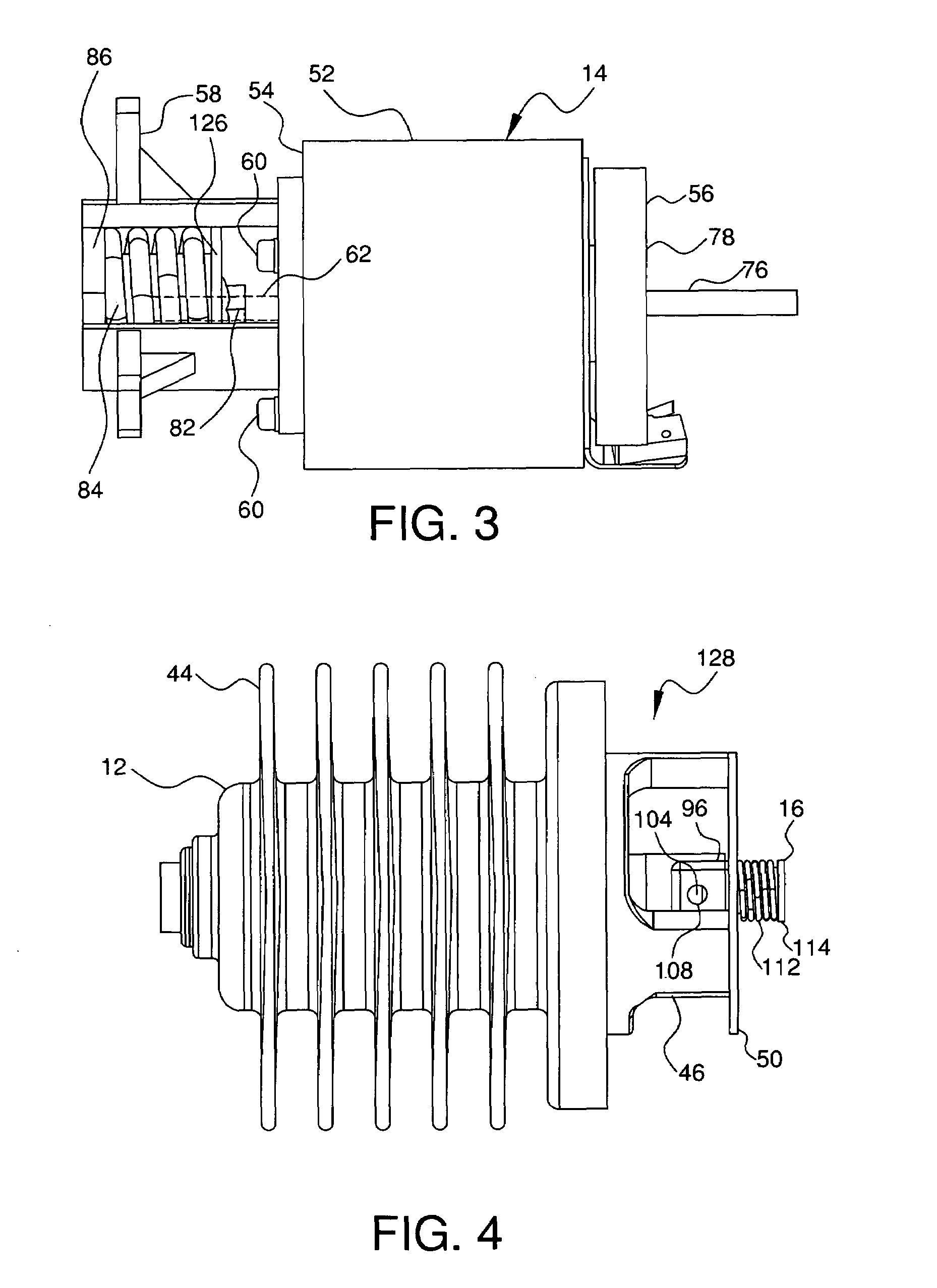
[0020]Referring to FIGS. 1–7, a circuit interrupting device 10 in accordance with an embodiment of the invention has a vacuum interrupter 12 connected to a solenoid assembly 14 by a turnbuckle and weld break assembly 16.

[0021]The vacuum interrupter 12 is conventional and therefore is only described in sufficient detail to allow one of ordinary skill in the art to make and use the present invention. The vacuum interrupter 12 provides voltage switching and includes a vacuum bottle 18 having a ceramic outer shell 20 with a first end 22 and a second opposing end 24. A stationary or primary contact 26 is fixed at the first end 22 and a movable contact 28 is slidably supported in an opening 30 at the second end 24. A seal (not shown) can be provided to ensure a vacuum is maintained in the vacuum bottle 18. The contacts 26, 28 are preferably made of a conductive material, such as copper. The movable contact 28 is connected to and operated by the solenoid assembly 14. When the stationary co...


PUM


Abstract

A circuit interrupting device has a circuit interrupter with a stationary contact and a moveable contact. The movable contact is movable relative to the stationary contact between a closed position that allows current to pass through the circuit interrupter and an open position separating the contacts and preventing current from passing through the circuit interrupter. The movable contact is controlled by a solenoid assembly. The movable contact is connected to a plunger of the solenoid assembly by a turnbuckle and weld break assembly. The turnbuckle and weld break assembly permits adjusting the contact wipe distance and generates a hammer force to break any welds between the contacts of the vacuum interrupter.

Description

CROSS-REFERENCE TO RELATED APPLICATIONS[0001]This application is a continuation-in-part of prior application Ser. No. 10 / 759,086, filed Jan. 20, 2004, now U.S. Pat. No. 6,852,939 and 10 / 759,087, filed Jan. 20, 2004; now U.S. Pat. No. 6,794,596 which are both divisionals of application Ser. No. 10 / 117,338, filed Apr. 8, 2002, now U.S. Pat. No. 6,753,493; which claims the benefit of U.S. Provisional Application No. 60 / 294,581, filed Jun. 1, 2001. The subject matter of each of these applications is incorporated herein by reference in its entirety.FIELD OF THE INVENTION[0002]The present invention relates to a device for interrupting an electrical circuit. More specifically, the present invention relates to a vacuum interrupter driven by a magnetic solenoid.BACKGROUND OF THE INVENTION[0003]Conventional circuit interrupting devices, such as circuit breakers, sectionalizers, and reclosers, provide protection for power distribution systems and the various apparatus on those power distributi...

Claims


Application Information

Patent Timeline
Patent Type & Authority Patents(United States)
IPC IPC(8): H01H1/48H01H1/50H01H75/00H01H1/58H01H3/22H01H9/00H01H9/08H01H33/02H01H33/66H01H33/666H01H71/12H01H75/04
CPCH01H33/6662H01H1/5822H01H3/001H01H3/227H01H9/0066H01H9/08H01H33/027H01H33/6606H01H71/123H01H75/04H01H2003/323H01H2033/6623H01H2033/6667
Inventor RHEIN, DAVID A.
Owner HUBBELL INC
Why Eureka
Try Eureka