
Proximity detaching for electronic article surveillance tags

Inactive Publication Date: 2007-05-08
TYCO FIRE & SECURITY GMBH
View PDF16 Cites 35 Cited by
  • Summary
  • Abstract
  • Description
  • Claims
  • Application Information

AI Technical Summary

Benefits of technology

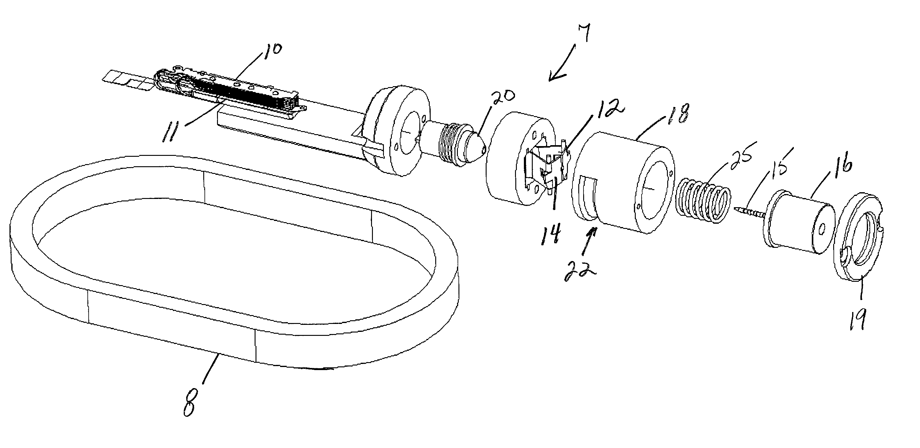
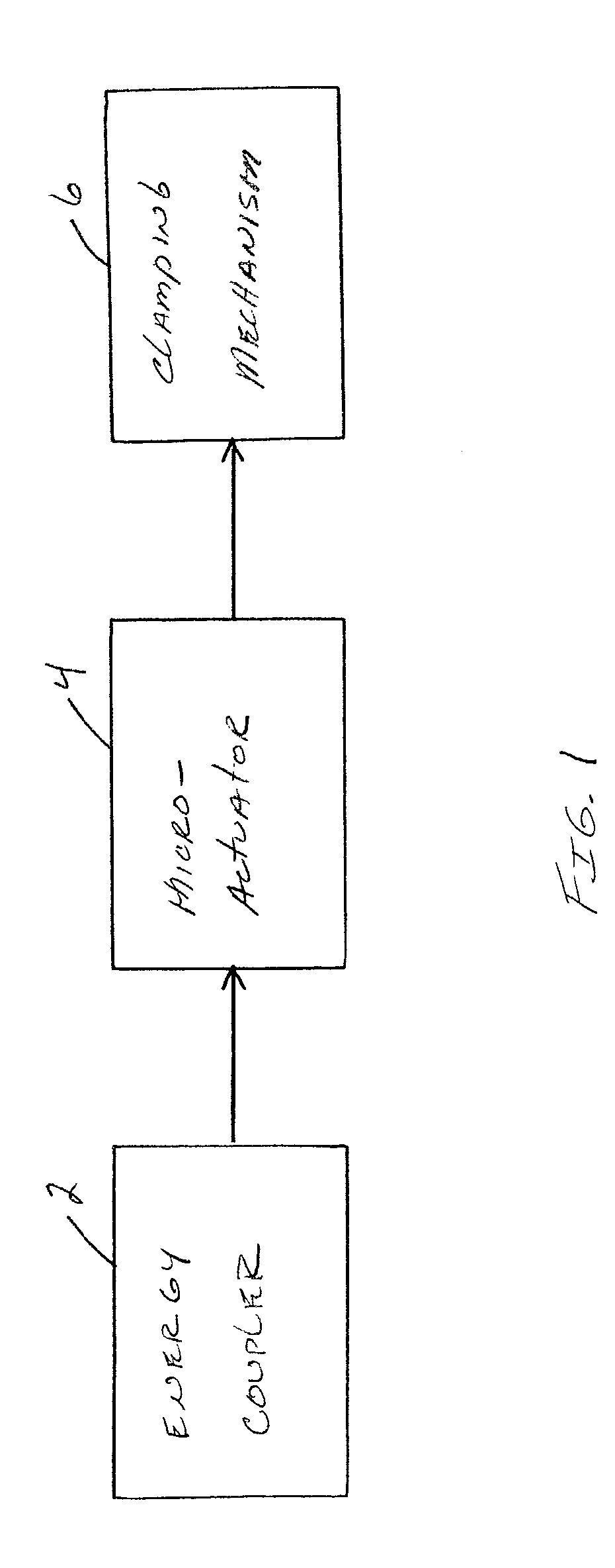
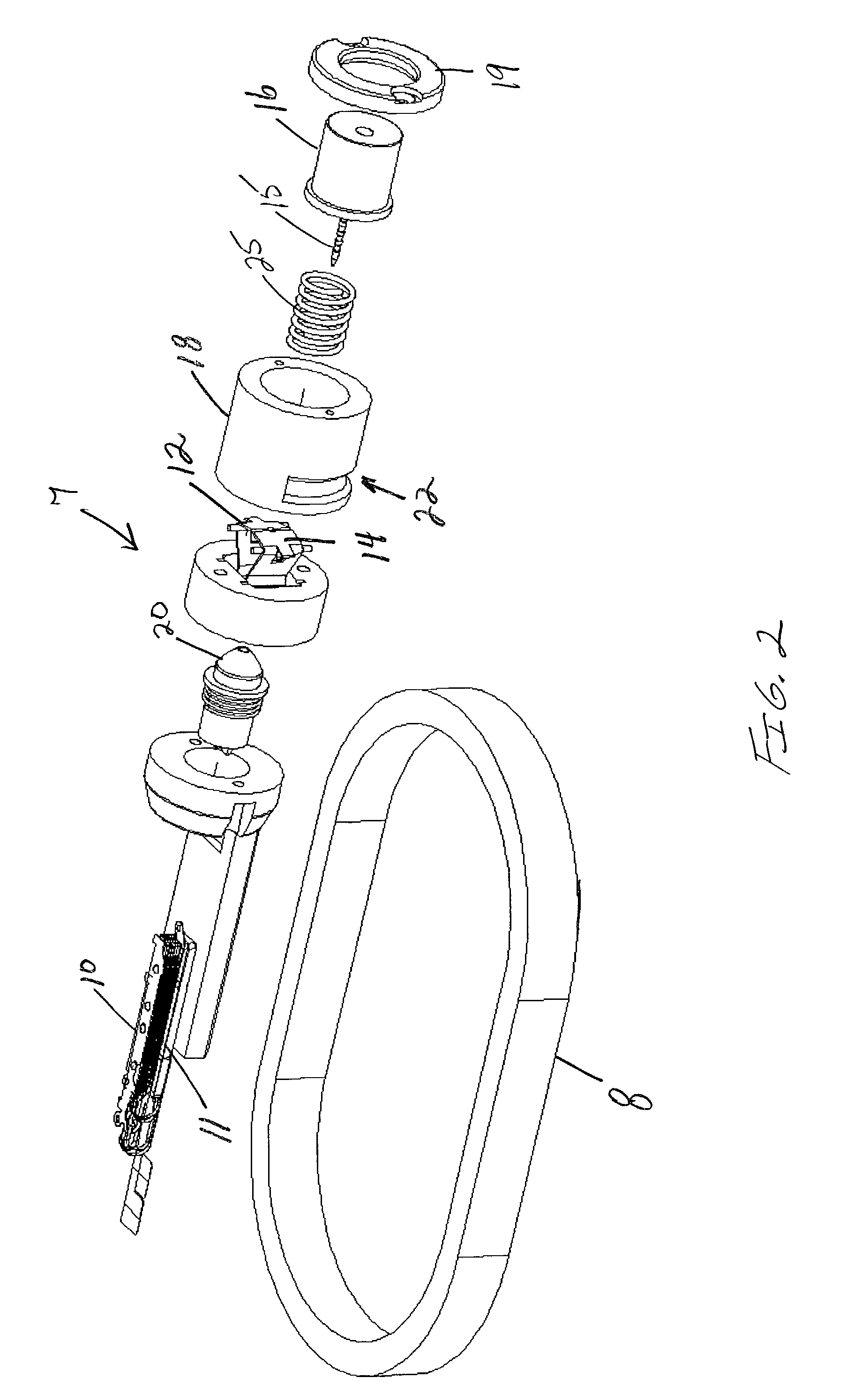
[0023]In one aspect, the EAS tag is detachable from an article by an electromagnetic signal, and includes an energy coupler for receiving energy from the electromagnetic signal. The energy coupler provides electrical energy in response to the electromagnetic signal. An actuator, connected to the energy coupler, converts the electrical energy to mechanical energy. A clamping mechanism, connected to the actuator, prevents release of the tag from an article to which the tag can be attached. The clamping mechanism is responsive to the mechanical energy to enable release of the tag from the article to which the tag can be attached.

Problems solved by technology

This locks the tack and the tag body forming the EAS tag to the article so that the tag and article cannot be readily separated from each other.
Such materials, however, are susceptible to being cut and damaged.
This tends to be a disadvantage, since it increases the likelihood that the locking feature of the tag can be separated from the EAS sensor part of the tag or can be exposed and defeated.
As a result, unauthorized removal of the compact disc with the frame causes an EAS sensor also incorporated into the frame, to generate a detectable signal for alarming an EAS system.
One drawback is that the linear slots leading to the spring clamp permit in-line viewing and access to the clamp.
This increases the susceptibility of the clamp to defeat, since linear objects can be inserted into the slots in an attempt to open the jaws.
Another drawback is that the fingers of the detacher are required to be of high precision, since they must be received in the region between the spring clamp jaws.
This increases the cost and complexity of the detacher.
The EAS tag of the '419 patent is more difficult to defeat than the above tags and is in worldwide use.

Method used


Image

  • Proximity detaching for electronic article surveillance tags
  • Proximity detaching for electronic article surveillance tags
  • Proximity detaching for electronic article surveillance tags

Examples


Embodiment Construction

[0047]Referring to FIG. 1, the invention includes an energy coupling device or energy coupler 2, a small or micro-actuator 4, and a mechanical locking or clamping mechanism 6, which are each fully described hereinbelow. Energy coupler 2 may be any device that receives transmitted energy, and coverts that energy into electrical energy. Energy coupler 2 may be an antenna or coil, such as an inductively coupled coil, with or without a magnetic core, that receives electromagnetic energy and transfers that collected energy to micro-actuator 4. Energy coupler 2 may alternately be a transducer that receives acoustic energy. Energy coupler 2 may alternately be a trigger mechanism and a battery. In that embodiment, the trigger mechanism would receive an electromagnetic signal, and switch the battery power to the micro-actuator 4. The transmitted signal, which may be an electromagnetic field or signal that notifies the tag of an authorized detaching of the tag, may be generated from existing ...


PUM


Abstract

A reusable EAS tag that is detachable from an article by placing the EAS tag in proximity to a detaching device is provided. The tag includes an energy coupler, a micro-actuator, and a clamping mechanism. The detaching device transmits a signal to the EAS tag to signal detachment, which is received by the energy coupler. The energy coupler converts the energy from the transmitted signal to electrical energy and delivers the electrical energy to the actuator. The actuator converts the electrical energy to mechanical energy to actuate the clamping mechanism and release the tag's locking or clamping mechanism for removal of the tag from the article to which it is attached.

Description

CROSS REFERENCES TO RELATED APPLICATIONS[0001]Not ApplicableSTATEMENT REGARDING FEDERALLY SPONSORED RESEARCH OR DEVELOPMENT[0002]Not ApplicableBACKGROUND OF THE INVENTION[0003]1. Field of the Invention[0004]This application relates to electronic article surveillance (EAS) tags, and more particularly to a reusable EAS tag that is proximity detached by electromagnetic energy.[0005]2. Description of the Related Art[0006]Electronic article surveillance systems are well known in the art and are used in many applications including inventory control and to prevent theft and unauthorized removal of articles from a controlled area. Typically, in such systems a system transmitter and a system receiver are used to establish a surveillance zone, which must be traversed by any articles being removed from the controlled area.[0007]An EAS tag is affixed to each article and includes a marker or sensor adapted to interact with a signal being transmitted by the system transmitter into the surveillanc...

Claims


Application Information

Patent Timeline
IPC IPC(8): G08B13/14E05B47/00E05B73/00
CPCE05B73/0017E05B73/0023E05B73/0052G08B13/2434E05B47/0009
Inventor HANSEN, NORMANSHAFER, GARY MARKEASTER, RONALD B.HOGAN, DENNISHANNES, ROYNARLOW, DOUGLAS A.PEREZ, SERGIOHO, WING
Owner TYCO FIRE & SECURITY GMBH
Learn More