Safety device for firearms

a safety device and firearm technology, applied in the field of safety devices for firearms, can solve the problems of many known firearm safety devices that cannot meet the needs of firearm owners, many are not adjustable enough to be used on a wide variety of firearms, and many known firearm safety devices can be removed, so as to prevent further sliding movement, prevent the assembly from being pulled apart, and increase the adjustability

Inactive Publication Date: 2007-05-15
CHILD GUARD
View PDF11 Cites 20 Cited by
  • Summary
  • Abstract
  • Description
  • Claims
  • Application Information

AI Technical Summary

Benefits of technology

[0009]The firearm safety device further includes a moveable clamp assembly. One embodiment includes a slide member having first and second posts disposed in a spaced apart relationship for receiving a portion of the trigger guard therebetween. A fastener is used to secure the slide member to the first or second assembly in a position to accommodate the trigger guard thereby preventing further sliding movement. The slide member may optionally include a plurality of apertures for receiving the second post thereby providing further adjustability. The moveable clamp assembly can include a cam having an eccentric outer surface connected to the first post to further increase the adjustability for different sized trigger guards, thereby accommodating many different firearms.
[0010]A plurality of apertures are formed in the first and second assemblies for receiving pins. One embodiment of the firearm safety device includes pins having a first end received in the first assembly apertures and a second end received in the second assembly apertures. One or more pins extend between the first and second assemblies in this manner. Another embodiment includes trigger guards having pins received in the apertures. The plurality of apertures allow the trigger guards to be positioned such that they are disposed adjacent the trigger for blocking access to and preventing actuation of a solid trigger.
[0011]A lip is disposed on portions of the periphery of one of the first or second assemblies for overlapping with the other of the first and second assemblies such that most of the periphery of the assemblies overlap when secured to the firearm except where the firearm is disposed adjacent thereto. The overlap prevents prying the assemblies apart when mounted to the firearm.

Problems solved by technology

However, for a variety of reasons typical known firearm safety devices do not meet the needs of firearm owners.
Many are not adjustable enough to be used on a wide variety of firearms.
Many known firearm safety devices can be removed too easily by a person not authorized to use the firearm, while others cannot be removed quickly enough by those who are.
Further, many firearm safety devices, even when secured to the firearm, do not adequately prevent discharging the firearm.

Method used


Image

  • Safety device for firearms
  • Safety device for firearms
  • Safety device for firearms

Examples


Embodiment Construction

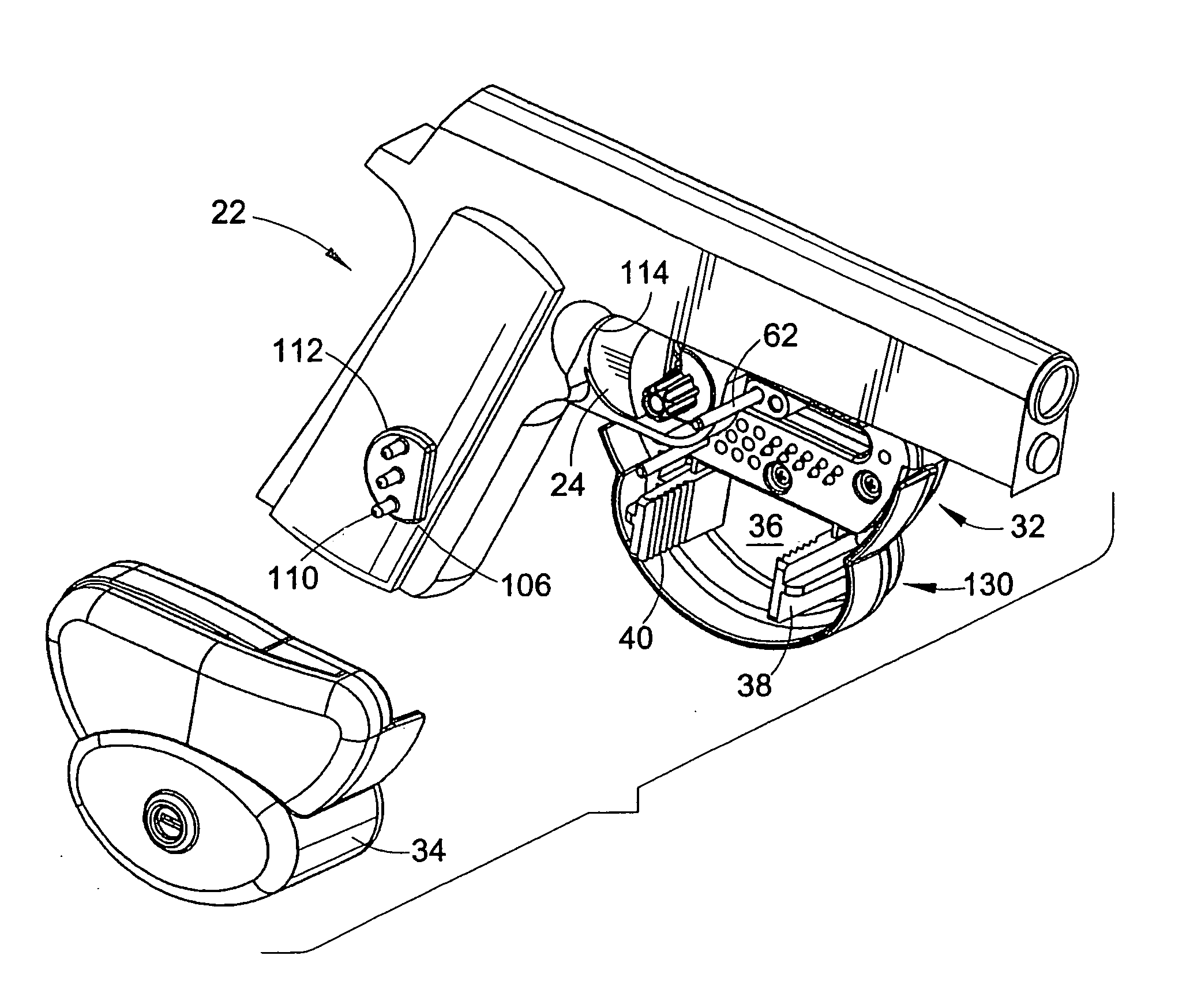
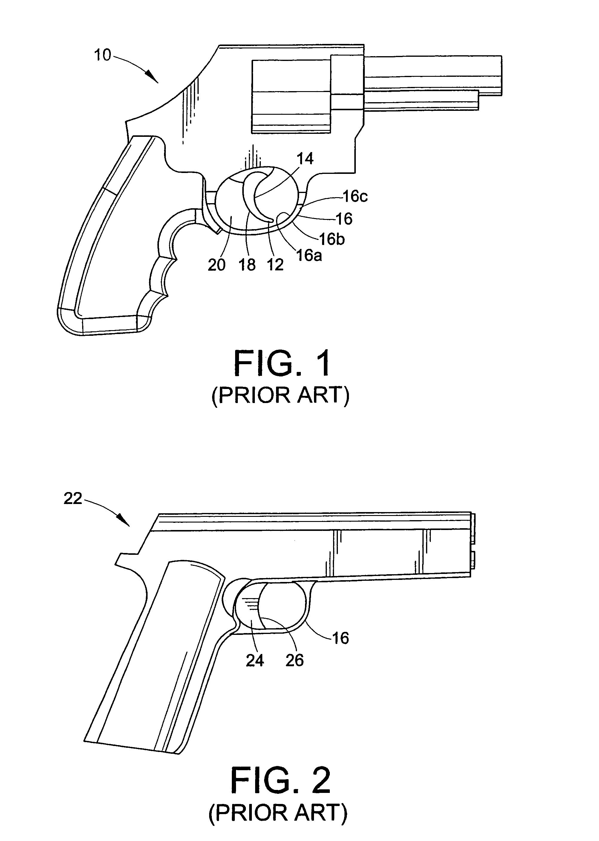
[0034]It is to be understood that the specific devices and processes illustrated in the attached drawings, and described in the following specification are simply exemplary embodiments of the inventive concepts defined in the appended claims. Hence, specific dimensions and other physical characteristics relating to the embodiments disclosed herein are not to be considered as limiting. It should be appreciated that the invention can be used for any suitable firearm 10, 22 having a trigger 12, 24 and trigger guard 16 including, but not limited to, pistols, revolvers, rifles, shotguns, carbines, etc.

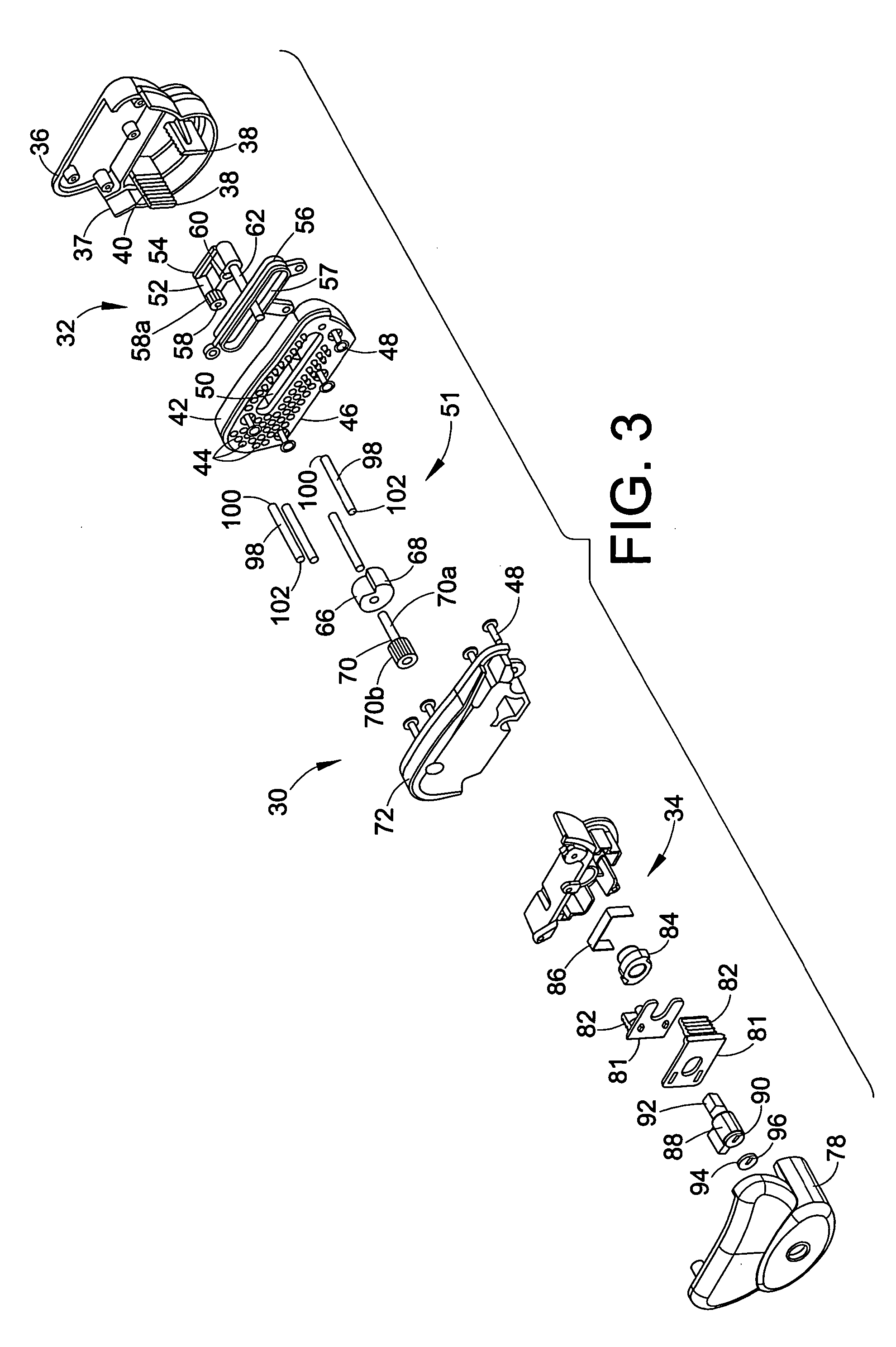
[0035]Referring now to FIGS. 3–5, a firearm safety device in accordance with the invention is shown generally at 30. The firearm safety device 30 includes a first assembly 32 and second assembly 34 adapted to be secured together adjacent opposite sides of the firearm trigger guard 16 as shall be described in further detail below. The first assembly 32 includes a housing 36 having a pair of ...


PUM


Abstract

A firearm safety device for a firearm having a trigger and trigger guard. The firearm safety device includes first and second assemblies adapted to be secured to the firearm on opposite sides of the trigger guard to prevent access to and actuation of the trigger. The firearm safety device includes a lip disposed on at least one of the first and second assemblies for overlapping the other assembly when the safety device is secured to the firearm.

Description

CROSS REFERENCE TO RELATED APPLICATIONS[0001]This application is a divisional application of U.S. patent application Ser. No. 09 / 927,063 filed Aug. 9, 2001 now U.S. Pat. No. 6,718,678 which is hereby incorporated herein by reference and which is a continuation in part of Ser. No. 09 / 499,539 filed Feb. 7, 2000 now U.S. Pat. No. 6,601,332 which is hereby incorporated herein by reference.BACKGROUND OF THE INVENTION[0002]The present invention relates to a safety device for firearms and more specifically a firearm safety device adapted to be secured to a firearm for preventing access to and actuation of the trigger.[0003]Referring to FIG. 1, a known firearm is shown generally at 10. The firearm includes a trigger 12 having a front portion 14 which is actuated or pulled to discharge the firearm 10. A trigger guard 16 extends from the firearm 10 and around the trigger 12 to help prevent unintended actuation of the trigger 12. The trigger guard includes an inside surface 16a, an outside sur...

Claims


Application Information

Patent Timeline
Patent Type & Authority Patents(United States)
IPC IPC(8): F41A17/00F41A17/54
CPCF41A17/54
Inventor RIEBLING, J. TERRYHUGHES, WILLIAM T.KOLTAS, DAVIDSCHAUB, BERNIE
Owner CHILD GUARD
Why Eureka
Try Eureka