Electrical enclosure system

a technology of enclosure system and electric power, which is applied in the direction of electrical apparatus casing/cabinet/drawer, positive displacement liquid engine, instruments, etc., can solve the problems of multiple components, time-consuming and costly installation, and insufficient protection of cables, etc., and achieves convenient access and simple structure

Active Publication Date: 2007-05-15
S J ELECTRO SYST INC
View PDF23 Cites 10 Cited by
  • Summary
  • Abstract
  • Description
  • Claims
  • Application Information

AI Technical Summary

Benefits of technology

[0012]In view of the foregoing disadvantages inherent in the known types of electrical enclosures now present in the prior art, the present invention provides a new electrical enclosure system construction wherein the same can be utilized for effectively containing a pump control and alarm system within a single protective structure and providing convenient access to the electrical components within.
[0018]A second object is to provide an electrical enclosure system for effectively containing a pump control and alarm system within a single protective structure and providing convenient access to the electrical components within.
[0019]Another object is to provide an electrical enclosure system that has a simple structure.
[0021]Another object is to provide an electrical enclosure system that provides lower manufacturing and installation costs.

Problems solved by technology

One problem with conventional electrical enclosures as shown in FIG. 1a is that they do not adequately protect the cables.
A further problem with conventional electrical enclosures as shown in FIG. 1a is that they require attachment of the enclosure to a post or other support structure.
A further problem with conventional electrical enclosures as shown in FIG. 1a is that they are time consuming and costly to install.
One problem with conventional electrical enclosures as shown in FIG. 1b is that they have multiple components required to be installed (tubular base, mounting bracket and cap).
A further problem with conventional electrical enclosures as shown in FIG. 1b is that they are time consuming and costly to install.
While these devices may be suitable for the particular purpose to which they address, they are not as suitable for effectively containing a pump control and alarm system within a single protective structure and providing convenient access to the electrical components within.
Conventional electrical enclosures for pump control and alarm systems are relatively complex in structure requiring a significant amount of time and labor to install and repair.

Method used


Image

  • Electrical enclosure system
  • Electrical enclosure system
  • Electrical enclosure system

Examples


Embodiment Construction

A. Overview

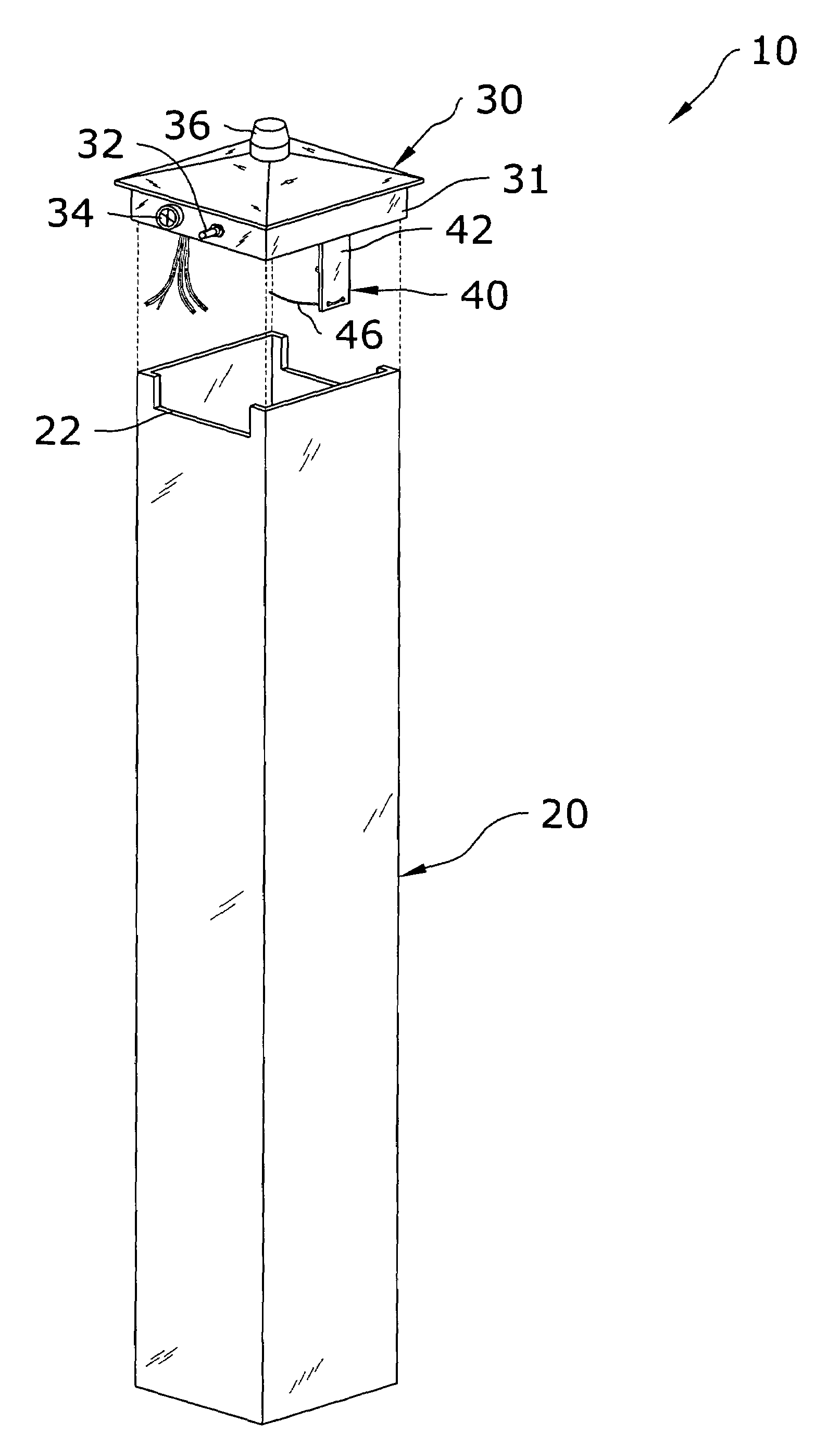
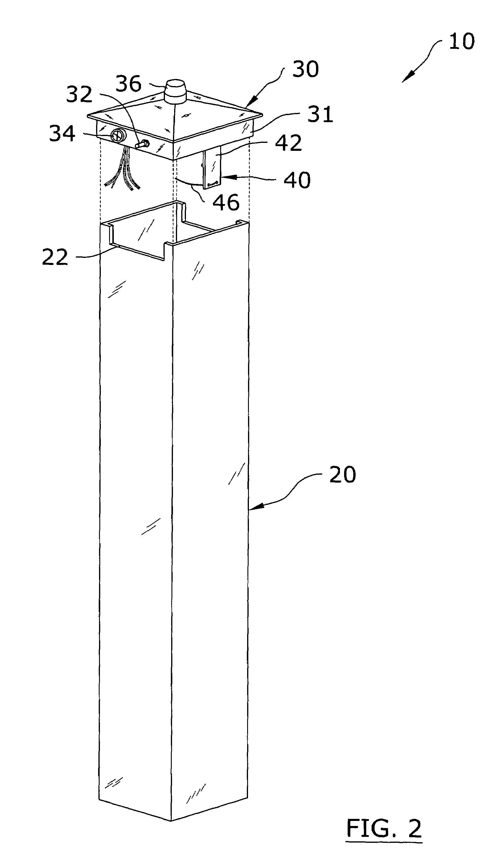
[0036]Turning now descriptively to the drawings, in which similar reference characters denote similar elements throughout the several views, FIGS. 2 through 10 illustrate an electrical enclosure system 10, which comprises a tubular pedestal 20 having an upper opening 22, and a cap 30 removably positioned within the upper opening 22 of the pedestal 20. The cap 30 contains electrical wiring and components for a pump control / alarm system 60. A bracket 40 is attached to the interior of the cap 30 for receiving and securing the cables extending from the pump control / alarm system 60 to a lower portion of the pedestal 20.

B. Pedestal

[0037]FIGS. 2, 3, 8 and 9 illustrate an exemplary tubular pedestal 20 suitable for usage with the present invention. As can be appreciated, the pedestal 20 may have various sizes, lengths and cross sectional shapes. The pedestal 20 is preferably designed to allow for the passage of a plurality of cables for the pump control / alarm system 60 as best ill...


PUM


Abstract

An electrical enclosure system for effectively containing a pump control and alarm system within a single protective structure and providing convenient access to the electrical components within. The electrical enclosure system includes a tubular pedestal having an upper opening, and a cap removably positioned within the upper opening of the pedestal. The cap contains electrical wiring and components for a pump control / alarm system. A bracket is attached to the interior of the cap for receiving and securing the cables extending from the pump control / alarm system to a lower portion of the pedestal.

Description

CROSS REFERENCE TO RELATED APPLICATIONS[0001]I hereby claim benefit under Title 35, United States Code, Section 119(e) of U.S. provisional patent application Ser. No. 60 / 538,995 filed Jan. 22, 2004. The 60 / 538,995 application is currently pending. The 60 / 538,995 application is hereby incorporated by reference into this application.STATEMENT REGARDING FEDERALLY SPONSORED RESEARCH OR DEVELOPMENT[0002]Not applicable to this application.BACKGROUND OF THE INVENTION[0003]1. Field of the Invention[0004]The present invention relates generally to electrical enclosures and more specifically it relates to an electrical enclosure system for effectively containing a pump control and alarm system within a single protective structure and providing convenient access to the electrical components within.[0005]2. Description of the Related Art[0006]Any discussion of the prior art throughout the specification should in no way be considered as an admission that such prior art is widely known or forms pa...

Claims


Application Information

Patent Timeline
Patent Type & Authority Patents(United States)
IPC IPC(8): H05K5/00H05K7/00
CPCH02B1/50H02G3/0493H02G9/10
Inventor STROZYK, RICHARD M.
Owner S J ELECTRO SYST INC
Why Eureka
Try Eureka