Optical fiber power splitter module apparatus

a technology of optical fiber and splitter, which is applied in the direction of instruments, optical waveguide light guides, optical light guides, etc., can solve the problems of general circuit administration and storage, tangling of fiber pigtails, and inconvenient use of fiber pigtails

Active Publication Date: 2007-05-15
FURAKAWA ELECTRIC NORTH AMERICA INC
View PDF3 Cites 105 Cited by
  • Summary
  • Abstract
  • Description
  • Claims
  • Application Information

AI Technical Summary

Problems solved by technology

With such a relatively large number of individual fiber pigtails, congestion and tangling of the fiber pigtails become concerns.
Also, accurate routing of the fiber pigtails and general circuit administration and storage are issues with these types of packaging structures.

Method used


Image

  • Optical fiber power splitter module apparatus
  • Optical fiber power splitter module apparatus
  • Optical fiber power splitter module apparatus

Examples


Embodiment Construction

[0015]In the following description like reference numerals indicate like components to enhance the understanding of the invention through the description of the drawings. Also, although specific features, configurations and arrangements are discussed hereinbelow, it should be understood that such is done for illustrative purposes only. A person skilled in the relevant art will recognize that other steps, configurations and arrangements are useful without departing from the spirit and scope of the invention.

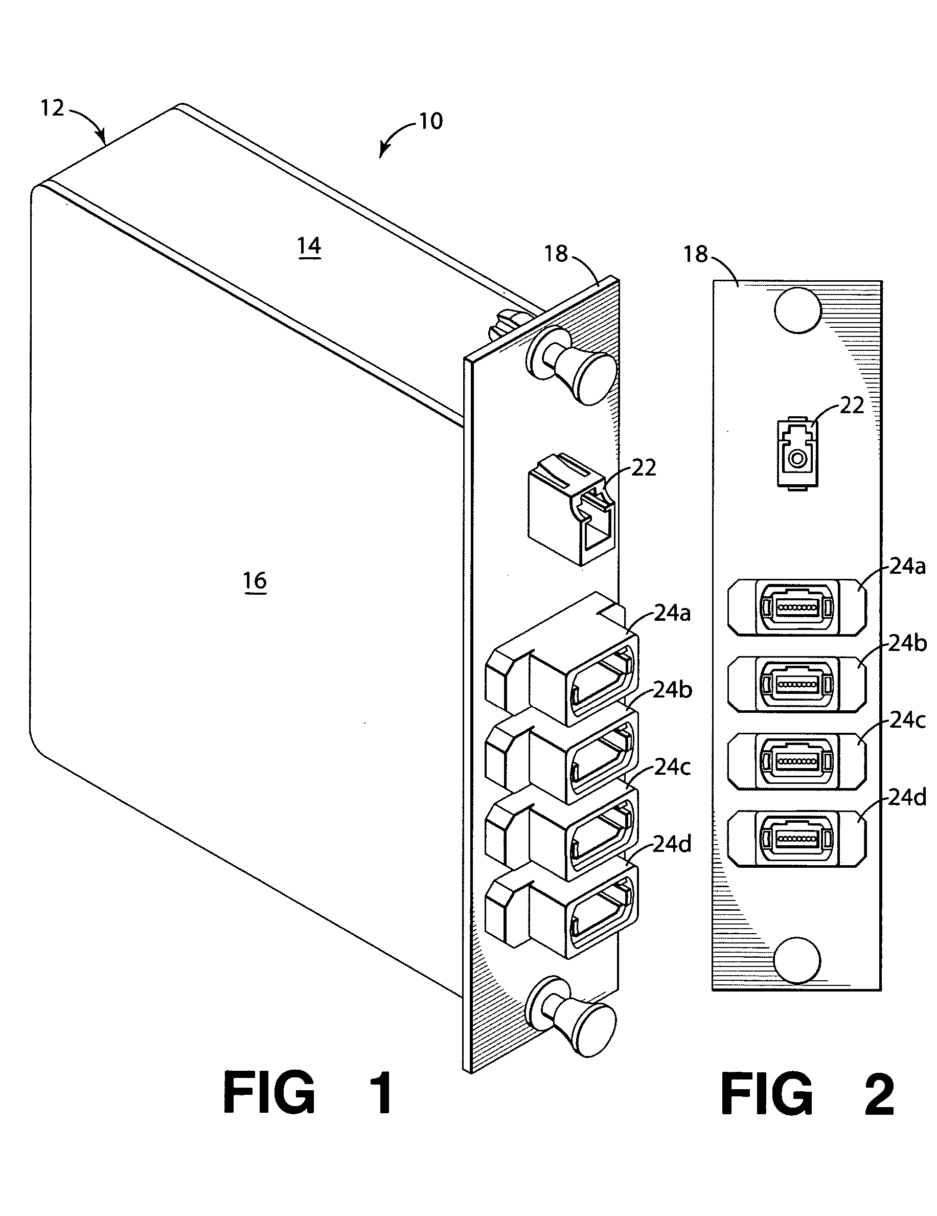
[0016]Referring now to FIG. 1, shown is a simplified, perspective view of an optical fiber power splitter module apparatus 10 according to embodiments of the invention. The module apparatus 10 is dimensioned and configured for housing and appropriately coupling the components used in splitting optical power from at least one single input fiber to one or more multi-fiber groups, according to embodiments of the invention. Also, the module apparatus 10 is dimensioned and configured f...


PUM


Abstract

Embodiments of the invention include an optical power splitting module apparatus. The module apparatus includes at least one input port, one or more multi-fiber output ports, and an optical fiber-splitter device coupled therebetween. The optical splitter device has a first end configured as at least one single optical fiber, and a second end configured as one or more multi-fiber groups. The first end of the splitter device is coupled to the input port and the second end of the splitter device is coupled to the output ports. The first end of the splitter device is, e.g., an LC connector. The second end of the splitter device is, e.g., one or more Multi-fiber Push On (MPO) connectors. The optical splitter device is, e.g., a 1×N planar lightwave circuit (PLC) splitter, such as a 1×32 PLC splitter with an LC input connector and four 8-fiber MPO output connectors.

Description

BACKGROUND OF THE INVENTION[0001]1. Field of Invention[0002]The invention relates to optical fiber power splitting devices. More particularly, the invention relates to modules for splitting optical power.[0003]2. Description of Related Art[0004]One of the most important recent developments in the field of fiber optic communications is the emergence of the feasibility of fiber management and distribution systems, arrangements and devices for delivering optical fiber signals to a particular location or group of locations. Such applications typically are referred to as Fiber To The x (FTTx) applications. One of the more popular FTTx applications is Fiber To The Premises (FTTP) or Fiber To The Home (FTTH), in which optical signal capabilities are routed from a central fiber office or other distribution location to a plurality of homes in that particular location via optical fiber and one or more optical connectors and / or other optical connection devices.[0005]One type of optical fiber c...

Claims


Application Information

Patent Timeline
Patent Type & Authority Patents(United States)
IPC IPC(8): G02B6/00
CPCG02B6/2804G02B6/4453G02B6/3897G02B2006/1215G02B6/46
Inventor FEUSTEL, CLAY A.HENDRICKSON, DANIELZHANG, HONGBO
Owner FURAKAWA ELECTRIC NORTH AMERICA INC
Why Eureka
Try Eureka