Fixing device

a fixing device and fixing roller technology, applied in the field of fixing devices, can solve the problems of bending deformation, damage to the end elastic deformation of the outside roller of the fixing roller, etc., and achieve the effect of maintaining the durability of the fixing roller

Active Publication Date: 2007-05-15
KONICA MINOLTA BUSINESS TECH INC
View PDF13 Cites 13 Cited by
  • Summary
  • Abstract
  • Description
  • Claims
  • Application Information

AI Technical Summary

Benefits of technology

[0009]An object of the present invention is therefore to provide a fixing device capable of suppressing bending deformation on both ends of an outside roller in a fixing roller when the fixing roller and a pressure roller rotate while the pressure roller is in contact with the fixing roller so as to prevent the ends of the fixing roller from being damaged and to enhance durability of the fixing roller.
[0012]According to the first aspect of the present invention, an axial length of the contact face of the pressure roller, which comes in contact with the outside roller in the fixing roller, is smaller than an axial length of the outside roller in the fixing roller. Therefore, when the fixing roller and the pressure roller rotate while the pressure roller is in contact with the fixing roller, both ends of the outside roller in the fixing roller is less susceptible to bending deformation (elastic deformation) caused by pressure of the pressure roller.
[0013]Thus, the bending deformation is decreased on both ends of the outside roller in the fixing roller. This suppresses generation of stress between the suppression member and the ends of the outside roller, and therefore, it becomes possible to prevent the ends of the fixing roller from being damaged and to enhance durability of the fixing roller.
[0016]According to the second aspect of the present invention, the fixing device is provided with a regulation member on both sides of the inside roller. Therefore, the regulation member prohibits the outside roller from moving, for example meandering or one-directional deviation, in the axial direction in relation to the inside roller when the outer roller and the pressure roller rotate in contact with each other.
[0018]According to the third aspect of the present invention, the pressure roller is shorter than the outside roller in the axial direction. Thus, the adhesion regions on both ends of the outside roller hardly receive the bending deformation caused by pressure of the pressure roller. This makes it possible to prevent the adhesive agent between both ends of the outside roller and the inside roller from coming off, so that durability of the fixing roller is maintained.

Problems solved by technology

Therefore, when the fixing roller and the pressure roller rotate while the pressure roller is in contact (pressurized contact) with the fixing roller, the outside roller of the fixing roller suffers elastic deformation caused by the pressure roller and develops bending deformation during rotation.
Thus, since both ends of the outside roller rotate while developing the bending deformation, stress is generated between both ends of the outside roller and the regulation member, which may cause damage on the ends of the fixing roller.

Method used


Image

  • Fixing device
  • Fixing device
  • Fixing device

Examples


first embodiment

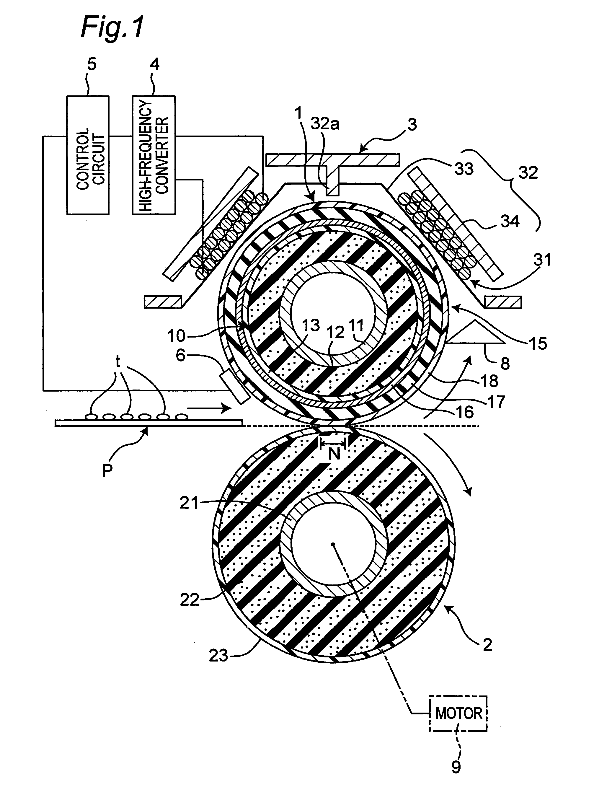
[0035]FIG. 1 is a cross sectional configuration view of a fixing device according to a first embodiment of the present invention. As shown in FIG. 1, the fixing device, which is of induction heating type, includes an electromagnetic induction heating-type fixing roller 1, a pressure roller 2 which contacts with the fixing roller 1 to form a nip N, and a magnetic flux generation means 3 disposed outside of the fixing roller 1 for generating magnetic flux.

[0036]The fixing roller 1 generates heat by virtue of magnetic flux from the magnetic flux generation means 3. Thereafter, a recording material P carrying an unfixed image t is passed through between the fixing roller 1 and the pressure roller 2. Thereby, the unfixed image t is melted and fixed (heated and fixed) to the recording material P while the recording material P is held and transported by the nip N.

[0037]The fixing device, together with an imaging means (unshown) for forming the unfixed image t on the recording material P, c...

second embodiment

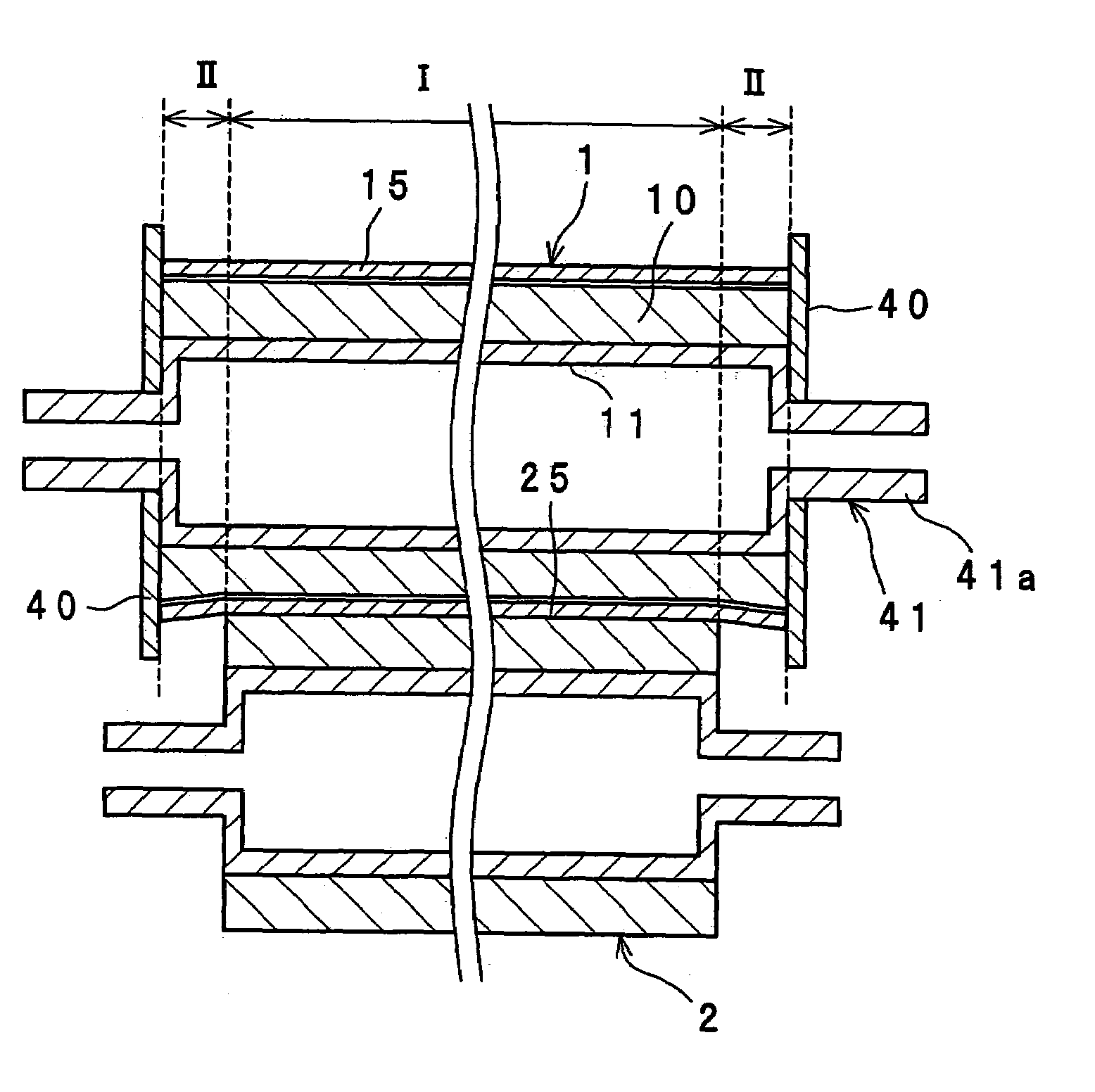
[0087]FIG. 4 shows a fixing device according to a second embodiment of the present invention. Description is given of the difference from the first embodiment. In the second embodiment, an edge 29 of the pressure roller 2 is not in a straight line form but in a wave form. Specifically, the edge 29 of the pressure roller 2 is a meandering curved line when viewed from a direction orthogonal to an axis of the pressure roller 2.

[0088]Thus, the outside roller 15 in the fixing roller 1 is less susceptible to developing creases and flaws when the pressure roller 2 presses the fixing roller 1 because the edge 29 of the pressure roller 2 is a meandering curved line. That is, damage is prevented in a boundary portion between the nip formation region I and the outside roller free region II as shown in FIG. 3.

[0089]On the contrary, in the case where the edge 29 of the pressure roller 2 is a straight line when viewed from the direction orthogonal to the axis of the pressure roller 2, the outside...

third embodiment

[0090]FIG. 5 shows a fixing device according to a third embodiment of the present invention. Description is given of the difference from the first embodiment. In the third embodiment, an edge between the end face 28 and the contact face 25 in the pressure roller 2 is formed into a convex curve face 26. In other words, the edge of the pressure roller 2 is roundly chamfered.

[0091]Since the edges of the pressure roller 2 have the convex curve face 26, it becomes difficult to form creases and flaws in the outside roller 15 of the fixing roller 1 when the pressure roller 2 presses the fixing roller 1. In other words, damage is prevented in the boundary portion between the nip formation region I and the outside roller free region II as shown in FIG. 3.


PUM


Abstract

A fixing device has a fixing roller including an inside roller, an outside roller and a regulation member. The regulation member is disposed outside of both ends of the outside roller in the axial direction to regulate axial movement of the outside roller. An axial length of the contact face, where the pressure roller contacts with the outside roller, is smaller than an axial length of the outside roller. Thereby, both ends of the outside roller hardly receive bending deformation caused by pressure of the pressure roller. This makes it possible to reduce stress exerted to both ends of the outside roller, and therefore, the ends of the fixing roller are prevented from being damaged to enhance durability of the fixing roller.

Description

CROSS-REFERENCE TO RELATED APPLICATIONS[0001]This application is based on application No. 2004-325382 filed in Japan, the entire content of which is hereby incorporated by reference.BACKGROUND OF THE INVENTION[0002]The present invention relates to a fixing device for use in an electrophotographic image forming apparatus such as a copier, a laser printer and a facsimile.[0003]In the fixing device, it has been considered to adopt an induction heating type of heat source which offers high thermal conversion efficiency in order to achieve energy saving. Particularly, from view-point of their compact design and high efficiency, attention is focus on the fixing device in which magnetic flux generated by coils is guided to a fixing roller by a core member such as ferrite cores.[0004]This conventional electromagnetic induction heating type of fixing device includes a fixing roller, a pressure roller which comes in contact with the fixing roller to form a nip, and a magnetic flux generation ...

Claims


Application Information

Patent Timeline
Patent Type & Authority Patents(United States)
IPC IPC(8): G03G15/20
CPCG03G15/2064
Inventor MIYAZAKI, MASAMI
Owner KONICA MINOLTA BUSINESS TECH INC
Why Eureka
Try Eureka