AI technical title is built by Patsnap AI team. It summarizes the technical point description of the patent document.
a detection device and force technology, applied in the field of force detection devices, can solve problems such as a complex three-way system
Active Publication Date: 2007-05-22
WACOH TECH INC
View PDF89 Cites 127 Cited by
Summary
Abstract
Description
Claims
Application Information
AI Technical Summary
This helps you quickly interpret patents by identifying the three key elements:
Problems solved by technology
Method used
Benefits of technology
Problems solved by technology
However priorly, regardless of the displacement detection type or the strain detection type, a force detection device of a considerably complex three-dimensional structure was required to detect the respective components independent of each other.
Method used
Image
Click on the blue label to locate the original text in one second.
Reading with bidirectional positioning of images and text.
Examples
first embodiment
[0226]The major structural parts of a force detection device of this invention shall now be described using FIG. 9 to FIG. 13, the operation principles of this device shall be described using FIG. 14A, FIG. 14B, and FIG. 15, the wiring for performing the detection in accordance to these operation principles shall be described using FIG. 16 to FIG. 21, and an electrode configuration suited for the detection of all six force components shall be described using FIG. 22 to FIG. 26.
[0227]FIG. 9 is a top view of this force detection device of the first embodiment. FIG. 10 shows a side view in section along sectioning line 10—10 of this top view and FIG. 11 shows a side view in section along sectioning line 11—11. As shown in FIG. 10 or FIG. 11, the basic components of this force detection device are a force receiving member 100, an intermediate member 200, and a supporting member 300, and the basic form of each of these is a plate-like member having a top surface of square shape. FIG. 10 ...
second embodiment
[0333]An example of a configuration of fixed electrodes for enabling the detection of all six components of Fx, Fy, Fz, Mx, My, and Mz is shown for the force detection device of the second embodiment in the top view of FIG. 36 (top view of supporting member 300). Each of fixed electrode sets E10, E20, E30, and E40 is comprised of eight fixed electrodes and this is because specific fixed electrodes have been split according to use in order to enable the detection of all six force components.
[0334]Enlarged views of the fixed electrode sets E10, E20, E30, and E40, shown in FIG. 36, are shown in FIG. 37, FIG. 38, FIG. 39, and FIG. 40, respectively. In each of these enlarged views, the gray hatching are provided to illustrate the electrode shapes clearly and do not indicate cross sections. As illustrated in these Figures, fixed electrodes E15, E25, E35, and E45, which respectively form Z-axis displacement detection capacitance elements, are formed at the central parts of the respective f...
PUM
Property
Measurement
Unit
receiving forces
aaaaa
aaaaa
force
aaaaa
aaaaa
flexibility
aaaaa
aaaaa
Abstract
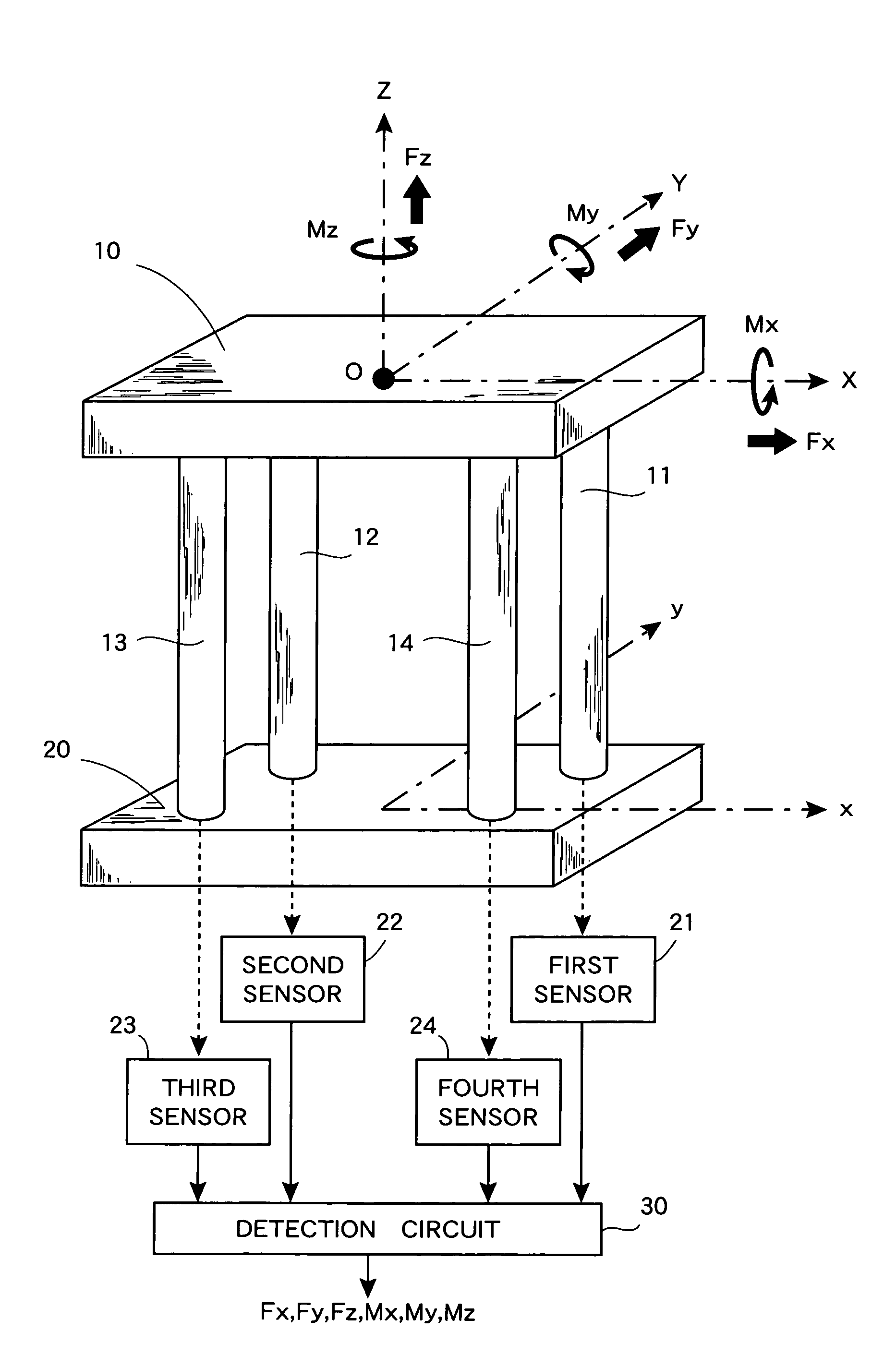
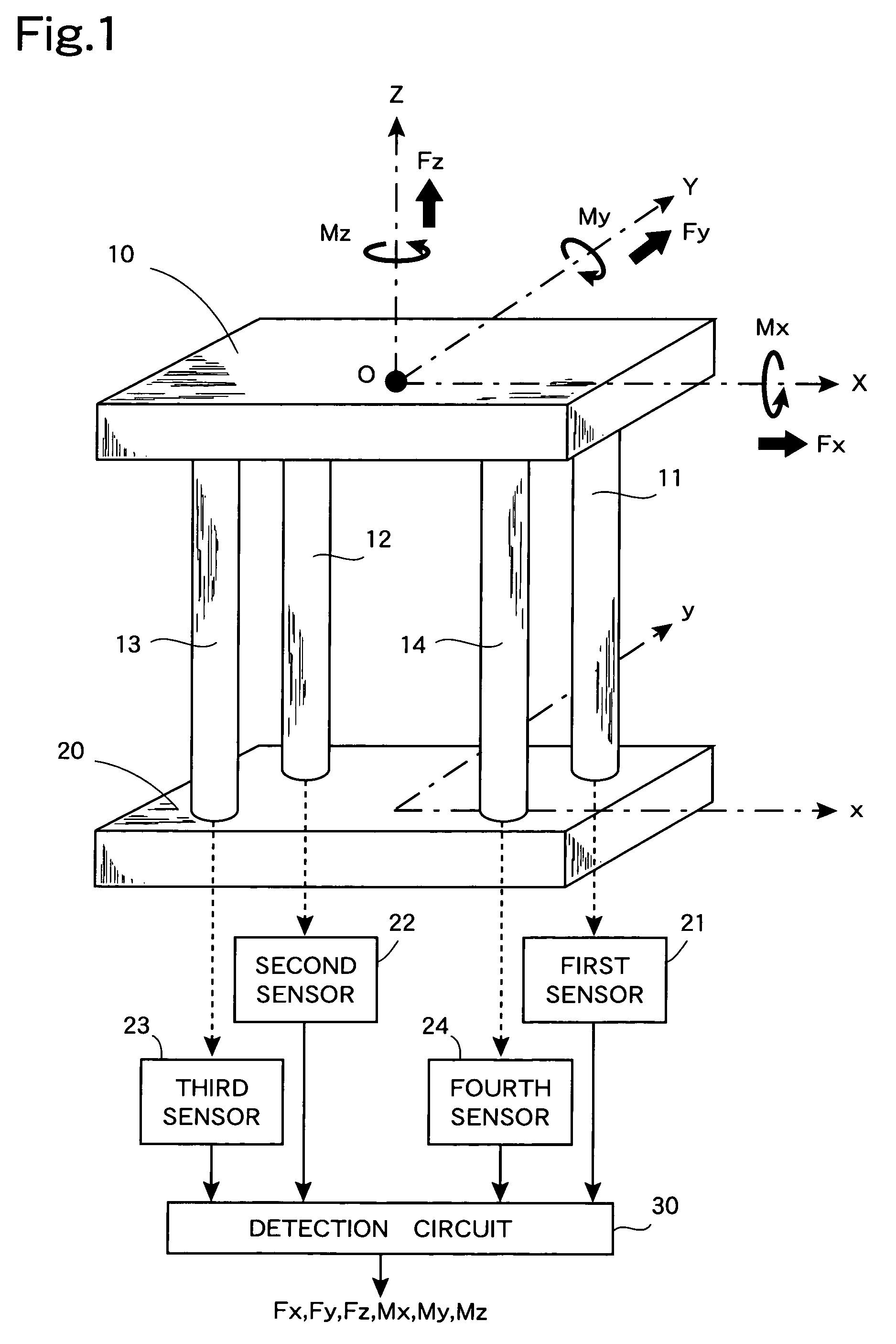
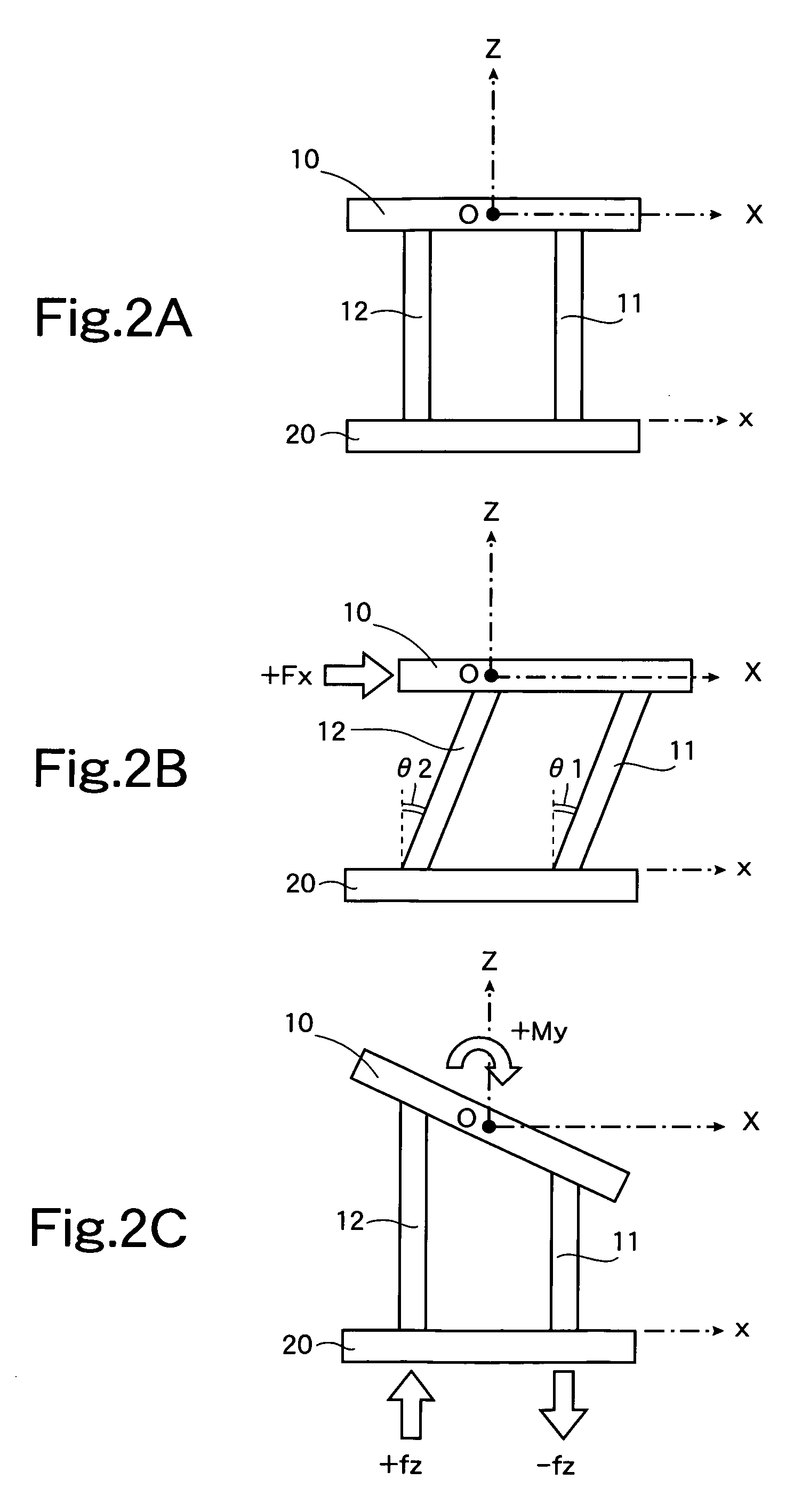
Forces and moments are detected in a distinguishing manner by a simple structure. A supporting member (20) is positioned below a force receiving member (10), which receives forces to be detected, and between these components, four columnar force transmitting members (11 to 14) are connected. Connecting members, having flexibility, are interposed at the upper and lower ends of each of the columnar force transmitting members (11 to 14) so that the columnar force transmitting members (11 to 14) can become inclined when the force receiving member (10) becomes displaced upon receiving a force. Sensors (21 to 24), each equipped with capacitance elements, are positioned at the connections parts of the respective columnar force transmitting members (11 to 14) and the supporting member (20) to detect forces that are transmitted from the respective columnar force transmitting members (11 to 14) to the supporting member (20). Based on the detection values of the sensors (21 to 24), a detection circuit (30) detects, in a distinguishing manner, forces and moments acting on the force receiving member (10). All of forces Fx, Fy, and Fz and moments Mx, My, and Mz can be detected.
Description
TECHNICAL FIELD[0001]This invention concerns a force detection device, and particularly concerns a force detection device suited for measuring forces and moments independently.BACKGROUND ART[0002]Various types of force detection devices are used for controlling the motions of robots and industrial machines. Compact force detection devices are also incorporated as man-machine interfaces of input devices for electronic equipment. In order to achieve miniaturization and cost reduction, a force detection device that is used in such an application is required to be as simple in structure as possible and yet enable forces of the respective coordinate axes in three-dimensional space to be detected independent of each other.[0003]Multi-axis force detection devices that are presently used can be classified into a type, with which specific directional components of a force that acts on a three-dimensional structure are detected as displacements that arise at a specific part, and a type, with ...
Claims
Application Information
Patent Timeline
Application Date:The date an application was filed.
Publication Date:The date a patent or application was officially published.
First Publication Date:The earliest publication date of a patent with the same application number.
Issue Date:Publication date of the patent grant document.
PCT Entry Date:The Entry date of PCT National Phase.
Estimated Expiry Date:The statutory expiry date of a patent right according to the Patent Law, and it is the longest term of protection that the patent right can achieve without the termination of the patent right due to other reasons(Term extension factor has been taken into account ).
Invalid Date:Actual expiry date is based on effective date or publication date of legal transaction data of invalid patent.

