System comprising a cam and a cam follower element and use of such a system
- Summary
- Abstract
- Description
- Claims
- Application Information
AI Technical Summary
Benefits of technology
Problems solved by technology
Method used
Image
Examples
first embodiment
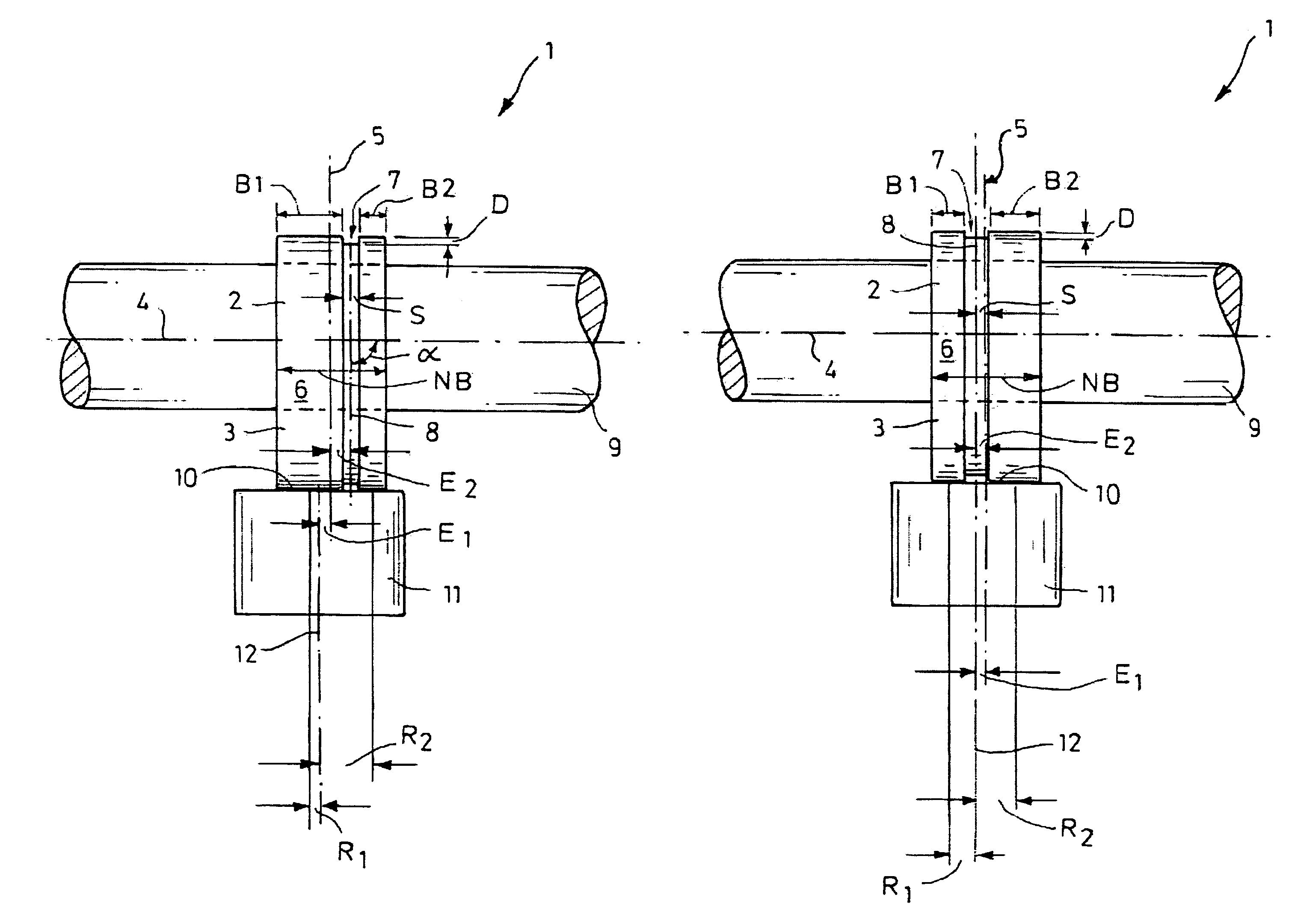
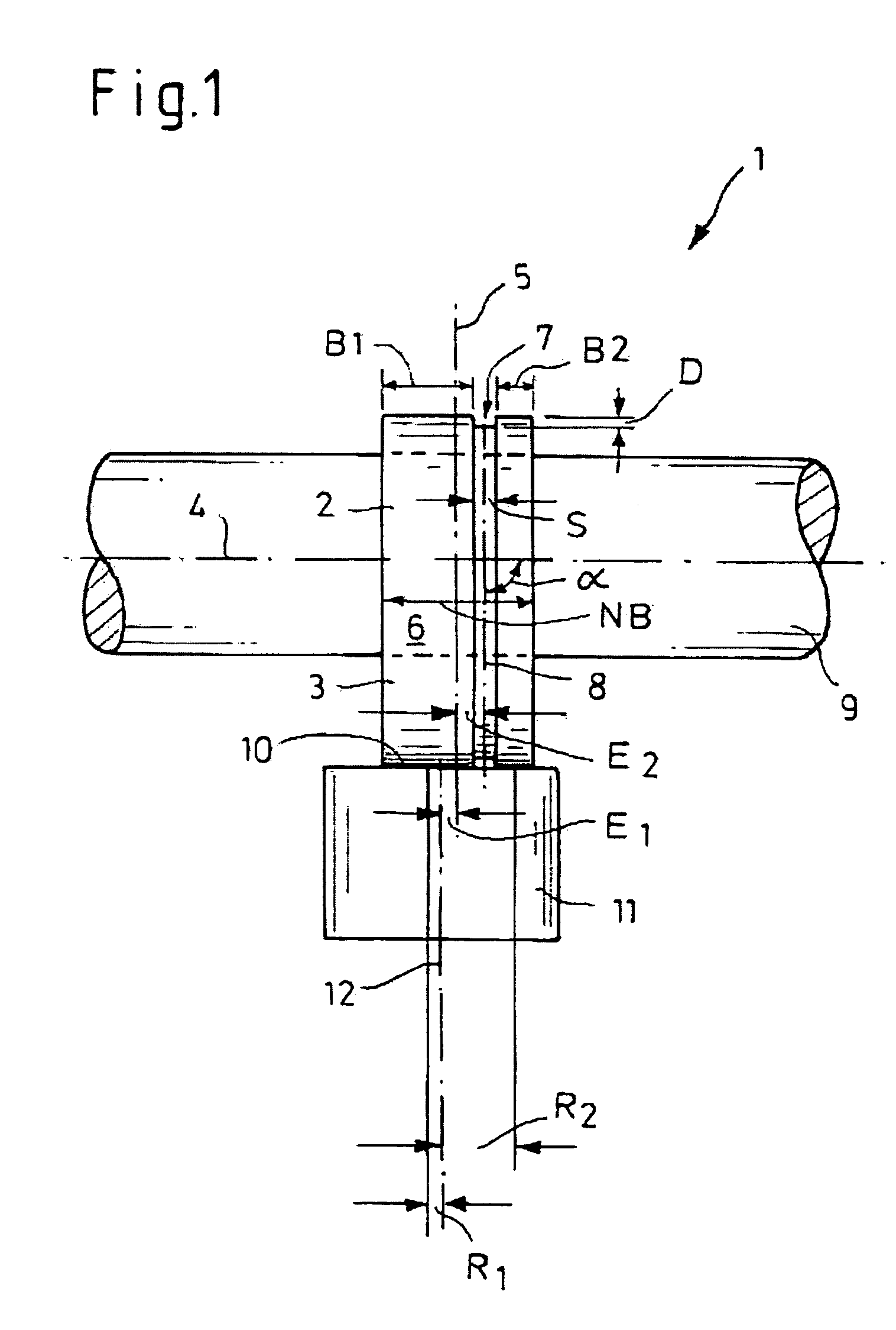
[0062]FIG. 1 is a schematic side view of the system 1, more specifically in a viewing direction perpendicular to the rotational axis 4 of the cam shaft 9 and perpendicular to the longitudinal axis 12 of the plunger 11.
[0063]The system 1 comprises a cam 2 with a cam lug 3 and a plunger 11. The cam 2 is arranged on a cam shaft 9 and rotates with this cam shaft 9 about its longitudinal axis 4.
[0064]The cam 2 and the plunger 11 are arranged with respect to one another in such a way that the central plane 5 of the cam 2, which plane extends perpendicularly with respect to the rotational axis 4 of the cam 2, is arranged offset with respect to the longitudinal axis 12 of the plunger 11 by an eccentricity E1 so that the plunger 11 rotates about its longitudinal axis 12 when the cam 2 is in engagement, with its cam outer face 6 along a contact line 10, with the plunger 11.
[0065]In the embodiment illustrated in FIG. 1, which corresponds to the example 1 specified in the table, the eccentricit...
second embodiment
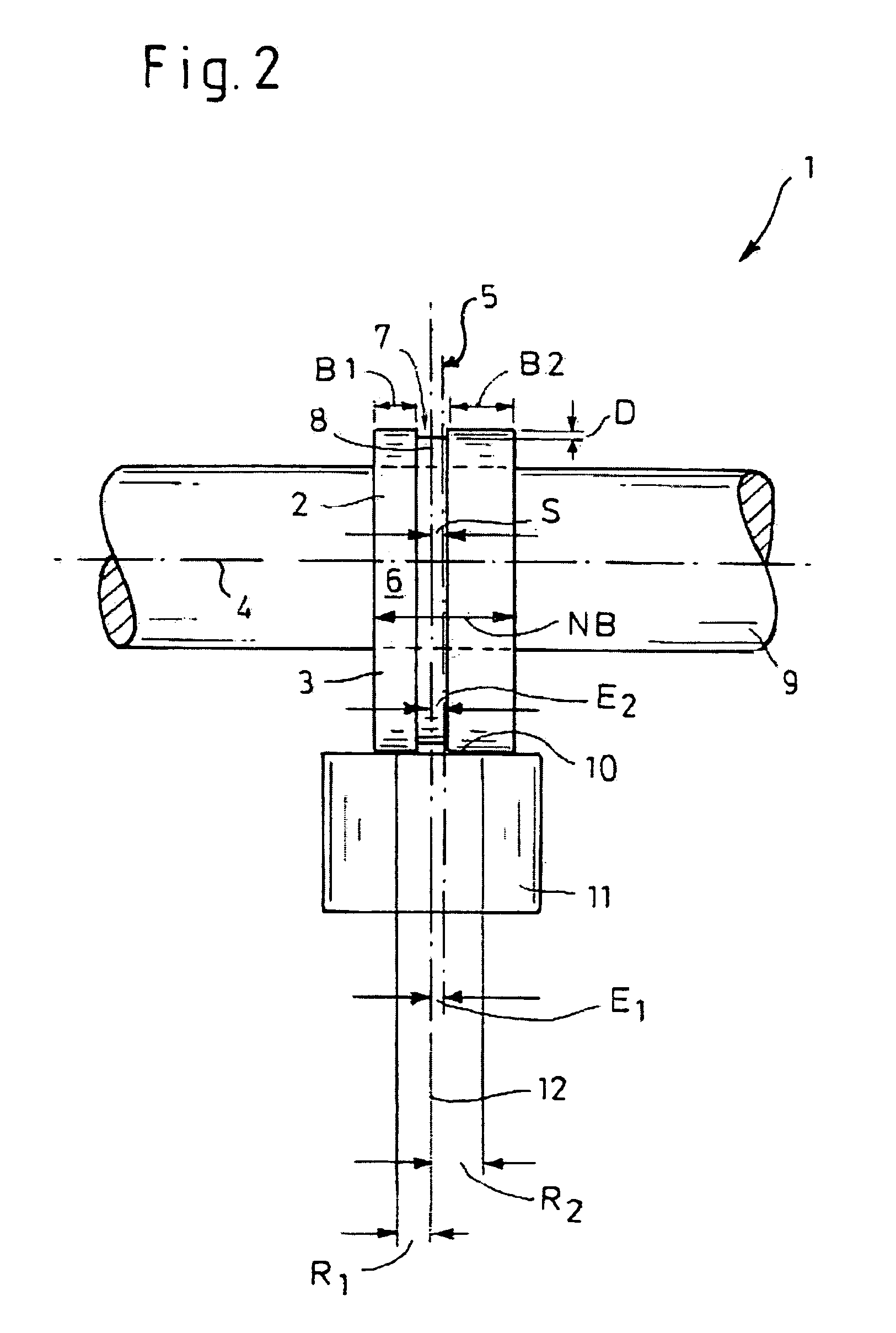
[0072]FIG. 2 is a schematic side view of the system 1.
[0073]In contrast to the embodiment illustrated in FIG. 1, the second embodiment is defined in that E1=−E2. The eccentricity E1 by which the central plane 5 of the cam 2 is arranged offset with respect to the longitudinal axis 12 of the plunger 11 corresponds in absolute terms to the eccentricity E2 by which the central line 8 of the groove 7 is arranged offset with respect to the central plane 5 of the cam 2, with the eccentricity E1 being positive, i.e. being directed to the left, while the eccentricity E1 is negative, i.e. is directed to the right. In this way the central line 8 of the groove 7 is aligned with the longitudinal axis 12 of the plunger 11.
[0074]This embodiment provides advantages because as a result the groove 7 is arranged in the area of the plunger surface in which the circumferential speed, which results from the product of the angular speed of the rotating plunger 11 and the distance from the longitudinal axi...
PUM
 Abstract
Description
Claims
Application Information
 - R&D
- Intellectual Property
- Life Sciences
- Materials
- Tech Scout
- Unparalleled Data Quality
- Higher Quality Content
- 60% Fewer Hallucinations
Browse by: Latest US Patents, China's latest patents, Technical Efficacy Thesaurus, Application Domain, Technology Topic, Popular Technical Reports.
© 2025 PatSnap. All rights reserved.Legal|Privacy policy|Modern Slavery Act Transparency Statement|Sitemap|About US| Contact US: help@patsnap.com


