System and method for damping vibration in a drill string

a vibration damping and drill string technology, applied in the field of underground drilling, can solve the problems of reducing the penetration rate of the drill bit into the drilling surface, causing substantial vibration and shock into the drill string, and premature failure of the various components of the drill string

Active Publication Date: 2007-05-22
APS TECH
View PDF27 Cites 85 Cited by
  • Summary
  • Abstract
  • Description
  • Claims
  • Application Information

AI Technical Summary

Benefits of technology

[0026]A preferred method for damping vibration of a drill bit comprises providing a valve assembly capable of exerting a viscous damping force on the drill bit, and controlling the viscous damping force in response to at least one operating parameter of the drill bit.

Problems solved by technology

The drilling environment, and especially hard rock drilling, can induce substantial vibration and shock into the drill string.
Such vibration can result in premature failure of the various components of the drill string.
Substantial vibration also can reduce the rate of penetration of the drill bit into the drilling surface, and in extreme cases can cause a loss of contact between the drill bit and the drilling surface.
These actions often do not effectively reduce the vibrations.
Reducing the weight-on-bit or the rotary speed of the drill bit usually reduces drilling efficiency.
Operating the drill bit off of its design point can reduce the performance and the service life of the drill bit.
Operating the shock sub outside of these conditions can render the shock sub ineffective, and in some cases can actually increase drill string vibrations.
Moreover, shock subs and isolators usually isolate the portions of the drill string up-hole of the shock sub or isolator from vibration, but can increase vibration in the down-hole portion of the drill string, including the drill bit.

Method used


Image

  • System and method for damping vibration in a drill string
  • System and method for damping vibration in a drill string
  • System and method for damping vibration in a drill string

Examples


Embodiment Construction

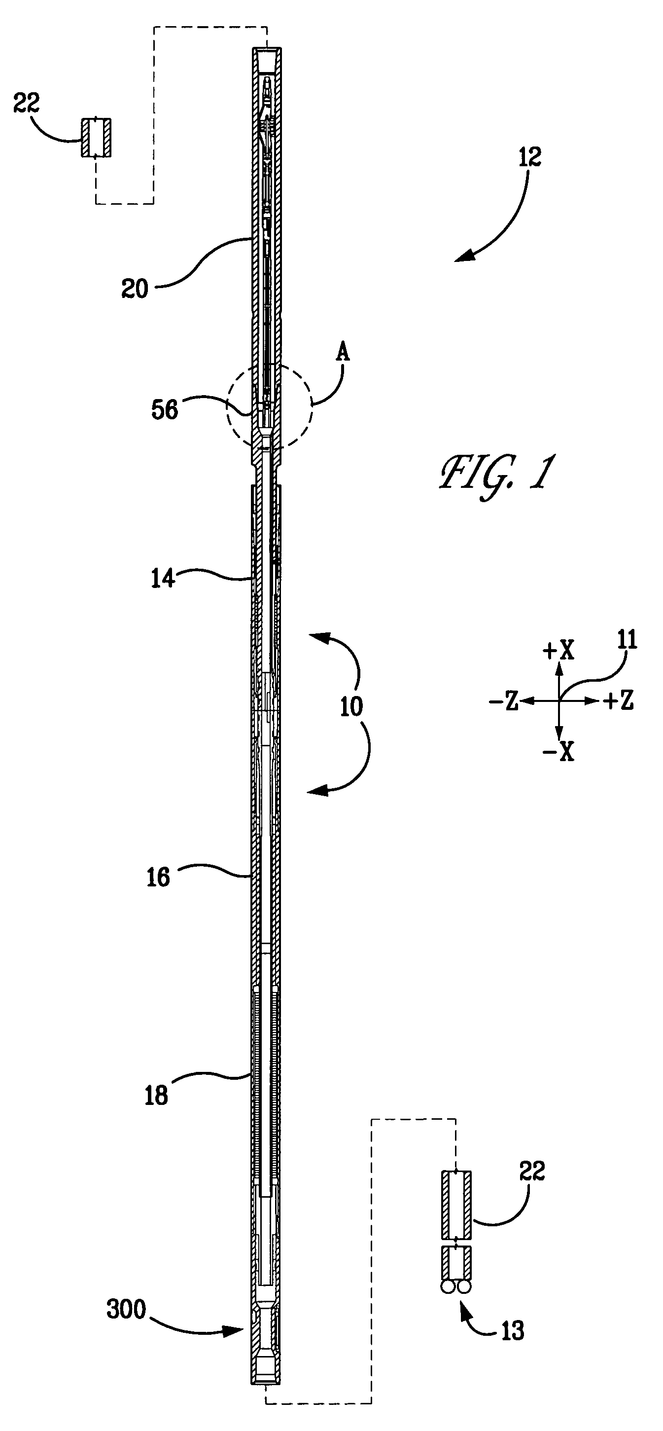
[0050]The figures depict a preferred embodiment of a vibration damping system 10. The figures are each referenced to a common coordinate system 11 depicted therein. The vibration damping system 10 can be used as part of a drill string 12, to dampen vibration of a drill bit 13 located at a down-hole end of the drill string 12 (see FIG. 1).

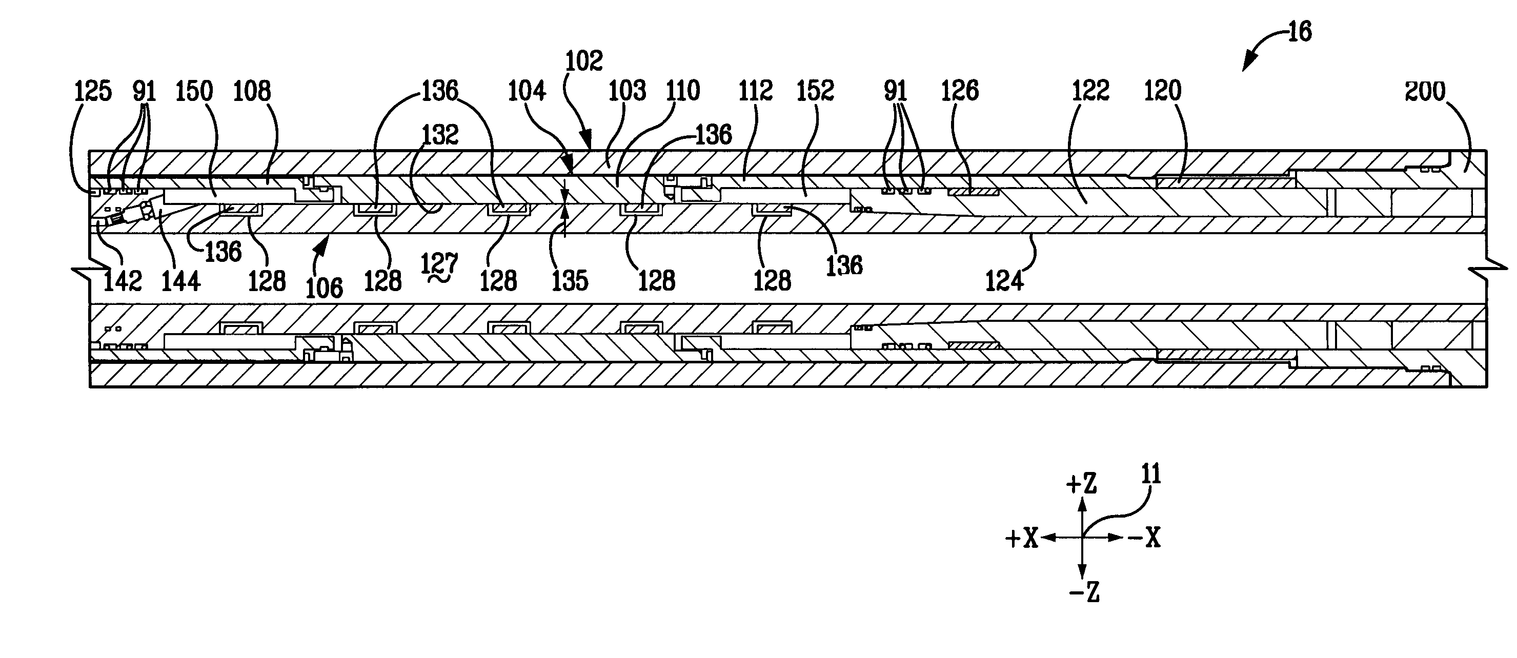
[0051]The vibration damping system 10 comprises a torsional bearing assembly 14, a valve assembly 16, and a spring assembly 18. The valve assembly 16 and the spring assembly 18 can produce axial forces that dampen vibration of the drill bit 13. The magnitude of the damping force can be varied by the valve assembly 14 in response to the magnitude and frequency of the vibration, on a substantially instantaneous basis. The vibration damping assembly 10 can be mechanically coupled to the drill bit by drill pipe 22 that forms part of the drill string 12.

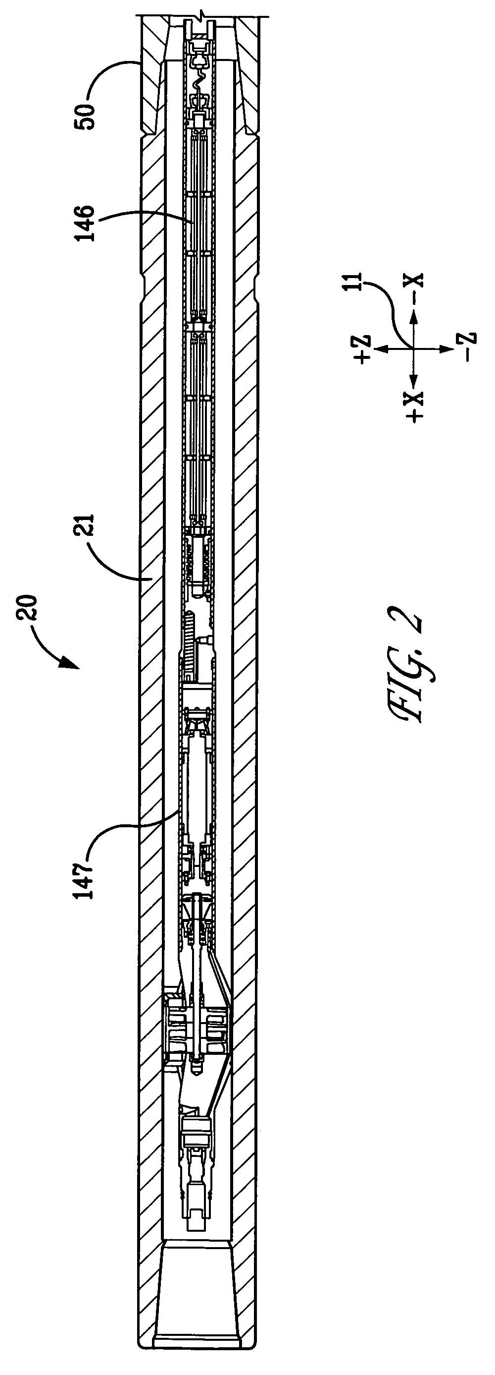
[0052]The torsional bearing assembly 14 can facilitate the transmission of drilling torque, while perm...


PUM


Abstract

A system for damping vibration in a drill string can include a valve assembly having a supply of a fluid, a first member, and a second member capable of moving in relation to first member in response to vibration of the drill bit. The first and second members define a first and a second chamber for holding the fluid. Fluid can flow between the first and second chambers in response to the movement of the second member in relation to the first member. The valve assembly can also include a coil or a valve for varying a resistance of the fluid to flow between the first and second chambers.

Description

CROSS REFERENCE TO RELATED APPLICATION[0001]This application claims priority under 35 U.S.C. § 119(e) to U.S. provisional application No. 60 / 518,116, filed Nov. 7, 2003, the contents of which is incorporated by reference herein in its entirety.[0002]Pursuant to 35 U.S.C. §202(c), it is acknowledged that the U.S. government may have certain rights to the invention described herein, which was made in part with funds from the Deep Trek program of the U.S. Department of Energy National Energy Technology Laboratory, Grant Number DE-FC26-02NT41664.FIELD OF THE INVENTION[0003]The present invention relates to underground drilling, and more specifically to a system and a method for damping vibration that occurs in a drill string during drilling operations.BACKGROUND OF THE INVENTION[0004]Underground drilling, such as gas, oil, or geothermal drilling, generally involves drilling a bore through a formation deep in the earth. Such bores are formed by connecting a drill bit to long sections of p...

Claims


Application Information

Patent Timeline
Patent Type & Authority Patents(United States)
IPC IPC(8): E21B41/00E21BE21B17/07E21B17/20E21B44/00
CPCE21B17/073E21B44/005E21B44/00F16F2224/045E21B17/20E21B34/00
Inventor WASSELL, MARK ELLSWORTHTURNER, WILLIAM EVANSBURGESS, DANIEL E.PERRY, CARL ALLISON
Owner APS TECH
Why Eureka
Try Eureka