Helmet lighting system

a technology for helmets and lights, applied in the direction of identification means, instruments, anti-theft devices, etc., can solve the problems of other motorists often losing track of the position of a nearby motorist, the risk and the danger of riding a motorcycle is generally higher

Inactive Publication Date: 2007-05-22
ZERO NINE DESIGN
View PDF13 Cites 52 Cited by
  • Summary
  • Abstract
  • Description
  • Claims
  • Application Information

AI Technical Summary

Benefits of technology

[0047]In yet another aspect, a helmet lighting system is disclosed for use on a vehicle. The lighting system comprises first and second accelerometers attached to the helmet, wherein the second accelerometer is positioned substantially perpendicular to the first accelerometer, and a light positioned on the helmet, the light responsive to signals from the first and second accelerometers. In the current aspect, the orientation of the first and second accelerometers aides in distinguishing helmet induced acceleration readings from actual vehicle acceleration readings.

Problems solved by technology

Unfortunately, the risks associated with riding a motorcycle are generally higher than driving an automobile for several reasons.
First, motorcycles are smaller than automobiles and other motorists often have a hard time seeing motorcycles on the roads.
Further, motorcycles are generally capable of higher rates of acceleration than automobiles causing other motorists to often lose track of the position of a nearby motorcycle.
Also, motorcycles are generally capable of higher rates of de-acceleration than automobiles causing motorcycles to often be hit from behind by motorists that are unable to stop in time.
Finally, motorcycles lack the weight, protective structure and other assorted safety devices such as airbags that are offered by automobiles.
While these safety precautions do provide some added safety, one of the most serious risks to two-wheeled vehicles is the fact that, as a result of the smaller size of the vehicle and minimized space for lighting systems, they are often very difficult to see.
However, the standard motorcycle brake light warning systems that are standard on motorcycles are inadequate when compared to the current systems used by other motor vehicles.
Because motorcycles have single light taillights, they are difficult for many motorists to judge safe distance.
Thus, the single taillight not only has a smaller illuminated area, but also detracts from the rider's ability to gauge distance.
This makes judging stopping distance more difficult for motorists even with good eyesight.
Because to the high horsepower to weight ratio of motorcycles, many motorcyclists decelerate without the use of brakes, often only applying the breaks at slow speeds to come to a full stop.
Thus, the motorcyclist may be decelerating without any warning to other motorists via the break light, resulting in decreased stopping distances when compared to similar situations with other moving vehicles.
However, these systems either require tapping into the existing break light wiring, or installing a sensor at the brake lever itself.
In addition to being costly and cumbersome to install, these systems also do not provide warning for non-brake induced deceleration.
However these systems have no ability to distinguish deceleration forces from helmet movement caused by the user.
Thus, these systems are ineffective as they result in excessive false positive readings.

Method used


Image

  • Helmet lighting system
  • Helmet lighting system
  • Helmet lighting system

Examples


Embodiment Construction

[0073]Referring more specifically to the drawings, for illustrative purposes the present invention is embodied in the apparatus generally shown in FIG. 1A through FIG. 8B and FIG. 9B through FIG. 19B. It will be appreciated that the apparatus may vary as to configuration and as to details of the parts, and that the method may vary as to the specific steps and sequence, without departing from the basic concepts as disclosed herein.

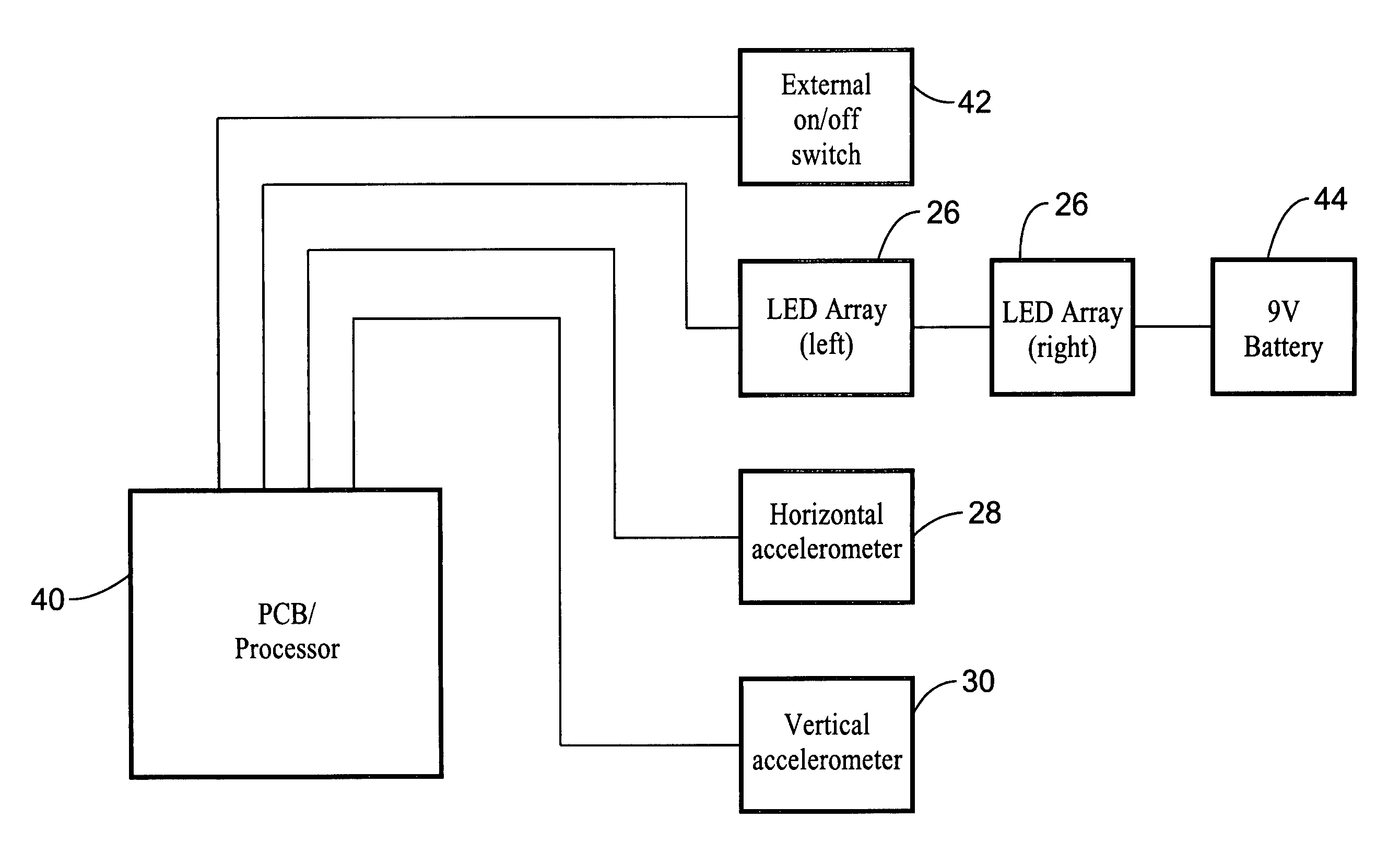
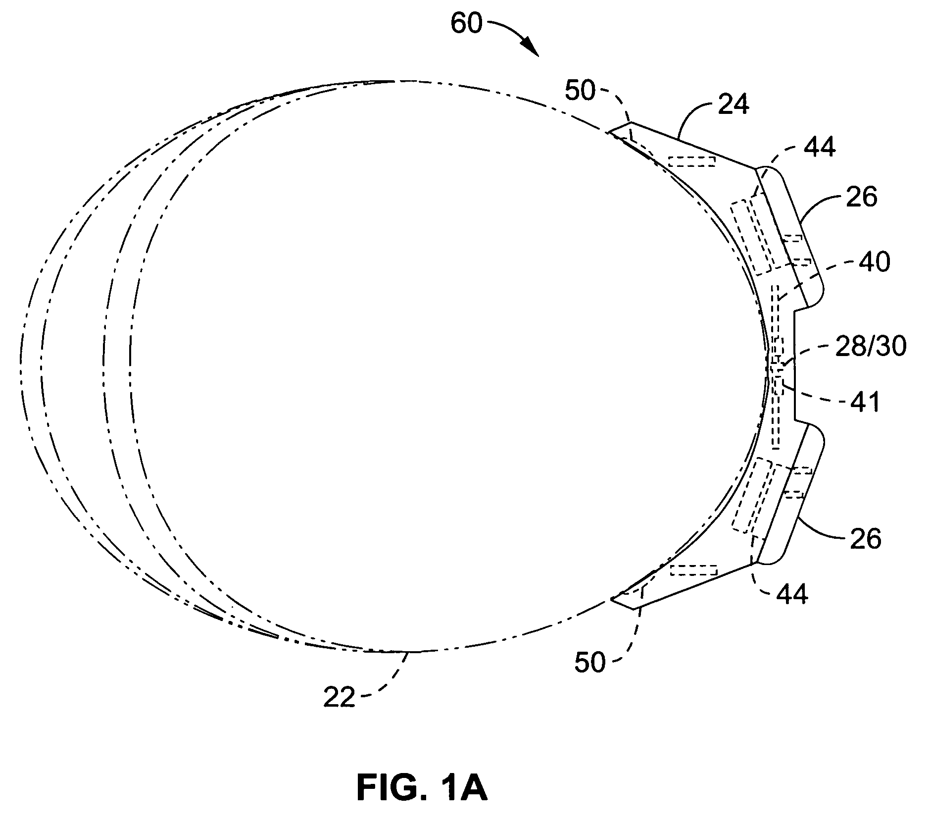
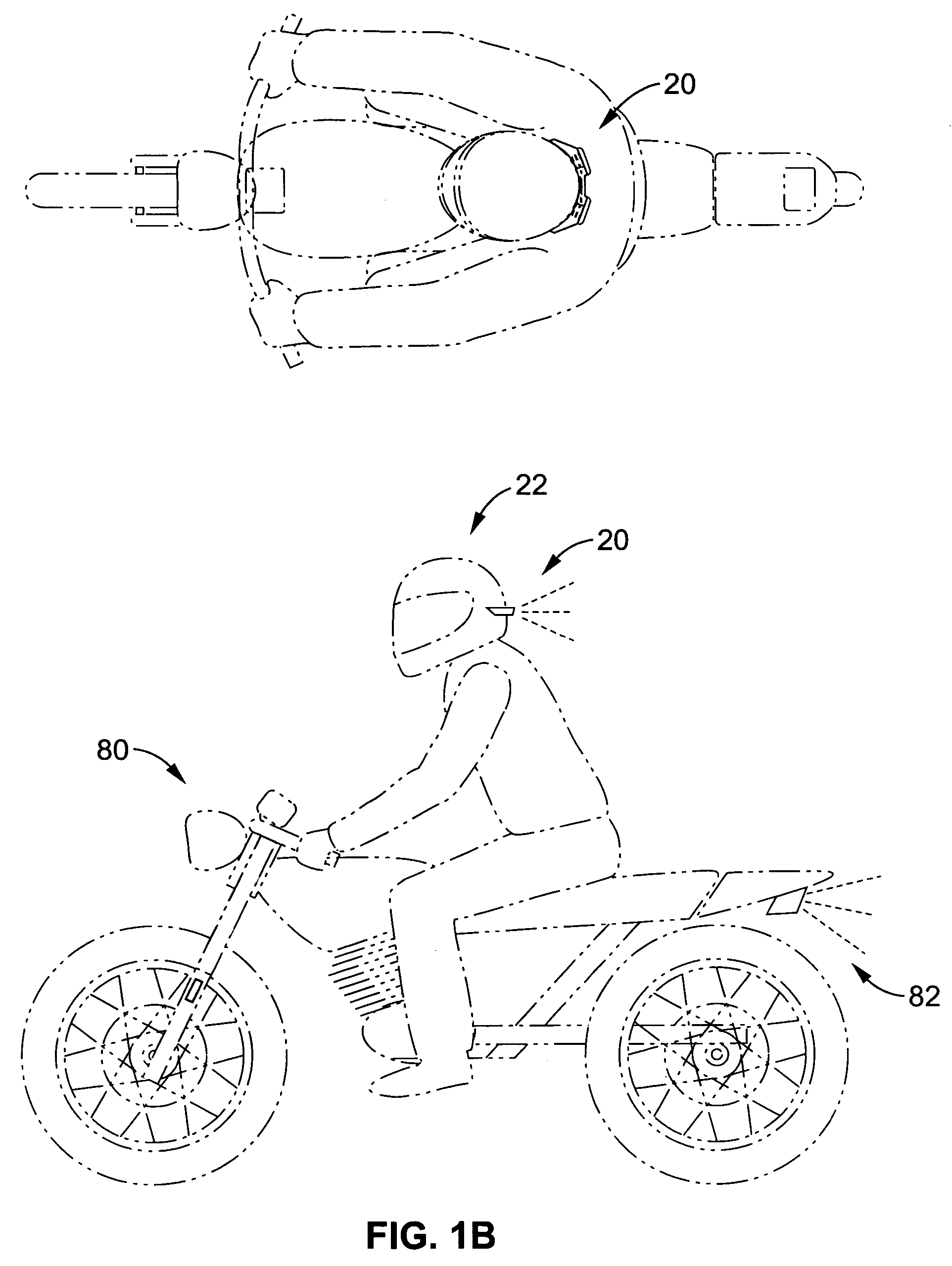
[0074]FIGS. 1A–3 illustrate a preferred embodiment of a completely self-contained brake light system 20 that fits to the back of your motorcycle or bicycle helmet 22. Light system 20 is stand-alone and requires no wiring or splicing into the vehicle's electrical system. Light system 20 includes a frame 24 that houses a pair of LED arrays 26. The frame is also configured to house one of more horizontally oriented accelerometers 28 and / or vertical accelerometers 30. The frame also houses an on / off switch 42 and power source 44, such as a dry-cell battery. Pow...


PUM


Abstract

A lighting system adapted to mount on a motorcycle or bicycle helmet. The lighting system includes a one or more accelerometers coupled to the helmet and a processor adapted to process the signals from the accelerometers. The accelerometers may be mounted to the helmet, or the motorcycle or bicycle. The lighting system further includes a light mounted on the helmet that is responsive to the processed signal such that the light illuminates as result of a deceleration force. The system may also include filtering software to remove helmet motion artifact and other noise from the signal. Remote wheel speed indicators may also be used in conjunction with or in place of the accelerometers. Mounting tabs may also be included to releasably attach the lighting unit to the helmet.

Description

CROSS-REFERENCE TO RELATED APPLICATIONS[0001]This application claims priority from U.S. provisional application Ser. No. 60 / 514,510 filed on Oct. 23, 2003, incorporated herein by reference in its entirety.STATEMENT REGARDING FEDERALLY SPONSORED RESEARCH OR DEVELOPMENT[0002]Not ApplicableINCORPORATION-BY-REFERENCE OF MATERIAL SUBMITTED ON A COMPACT DISC[0003]Not ApplicableNOTICE OF MATERIAL SUBJECT TO COPYRIGHT PROTECTION[0004]A portion of the material in this patent document is subject to copyright protection under the copyright laws of the United States and of other countries. The owner of the copyright rights has no objection to the facsimile reproduction by anyone of the patent document or the patent disclosure, as it appears in the United States Patent and Trademark Office publicly available file or records, but otherwise reserves all copyright rights whatsoever. The copyright owner does not hereby waive any of its rights to have this patent document maintained in secrecy, inclu...

Claims


Application Information

Patent Timeline
Patent Type & Authority Patents(United States)
IPC IPC(8): B62J3/00A42B3/04B60Q1/26B60Q1/44B60Q1/50B62J6/04
CPCA42B3/0453B60Q1/2676B60Q1/44B62J6/04B60Q2900/30B62J2006/008B62J6/045B62J6/165
Inventor MOORE, DAVIDHEBERT, JOHN D.KNAPP, R. BENJAMINGREENE, RICHARDLOH, DEREK
Owner ZERO NINE DESIGN
Why Eureka
Try Eureka