
Image recording apparatus and test pattern for evaluating recorded image

a recording apparatus and recording technology, applied in the field of image recording apparatus, can solve the problems of insufficient image quality, inability to perform visualization, and insufficient image quality, so as to achieve easy density measurement and evaluate image quality

Inactive Publication Date: 2007-05-22
KONICA CORP
View PDF5 Cites 16 Cited by
  • Summary
  • Abstract
  • Description
  • Claims
  • Application Information

AI Technical Summary

Benefits of technology

[0011]Further, another object of the invention is to provide an image recording apparatus for recording the test pattern that is sufficient for physical evaluation such as granularity and sharpness and makes the density measurement to be easy.
[0012]Further object is to provide an image recording apparatus capable of recording the test pattern for combined evaluation that can evaluate image quality of an image objectively.
[0131]The image-recording apparatus of item 59 is represented by a test pattern that is recorded on a recording medium from the image recording apparatus stated above for evaluating sharpness of the image recording apparatus, wherein a pattern element equipped with four or more different spatial frequency sections is provided, and the test pattern for evaluating sharpness in which 1–20 cycles are arranged continuously can be recorded, and thereby, evaluation of sharpness can be conducted properly by the test pattern.
[0192]Since the image-recording apparatus of item 61 is characterized in that a storage means that stores a plurality of image data corresponding to the structure of a part of a human body or to a test pattern wherein the aforesaid structure is copied, a selecting means that selects at least one of the aforesaid image data in accordance with a connected radiographing equipment, and a recording means that records a test pattern on a recording medium based on the selected image data, are provided, it is possible to select the image that is closest in terms of a shape to the image to be outputted in accordance with a radiographing apparatus that is intended to output images, for example, which makes it possible to evaluate more properly.

Problems solved by technology

However, even if images obtained through radiographing are stored in a form of a digital signal, a form for visualization is a problem.
Namely, when radiation images are offered for diagnoses made by medical doctors, image quality, which is the same as that of a household printer, is not sufficient, and image forming at higher image quality is needed.
In an image recording apparatus for recording the medical images as stated above, it is a problem how to make the initial image quality forming capability to be high, and to keep the initial capability for a long time.
For example, if a user can judge that image quality of outputted images is deteriorated by sudden deterioration of recording accuracy caused by some troubles of the image recording apparatus, the user has only to request the maintenance each time.
However, when image quality is lowered gradually day after day, the user sometimes fails to judge the deterioration of image quality, and further, when the user cannot identify the cause of the deterioration of image quality, it sometimes takes a long time to identify the cause before the start of repair.
Though the gradation can be evaluated by this test pattern, the test pattern is not suitable for physical evaluation such as granularity and sharpness.
However, it has a problem that it is not suitable for measurement because it is not an exclusive test pattern for obtaining physical evaluation values such as root mean square (RMS) and Weiner spectrum (WS).
However, it has a problem that it is not suitable for measurement because it is not an exclusive test pattern for obtaining physical evaluation values such as sine wave response filter (SWRF) and modulation transfer function (MTF).

Method used


Image

  • Image recording apparatus and test pattern for evaluating recorded image
  • Image recording apparatus and test pattern for evaluating recorded image
  • Image recording apparatus and test pattern for evaluating recorded image

Examples


Embodiment Construction

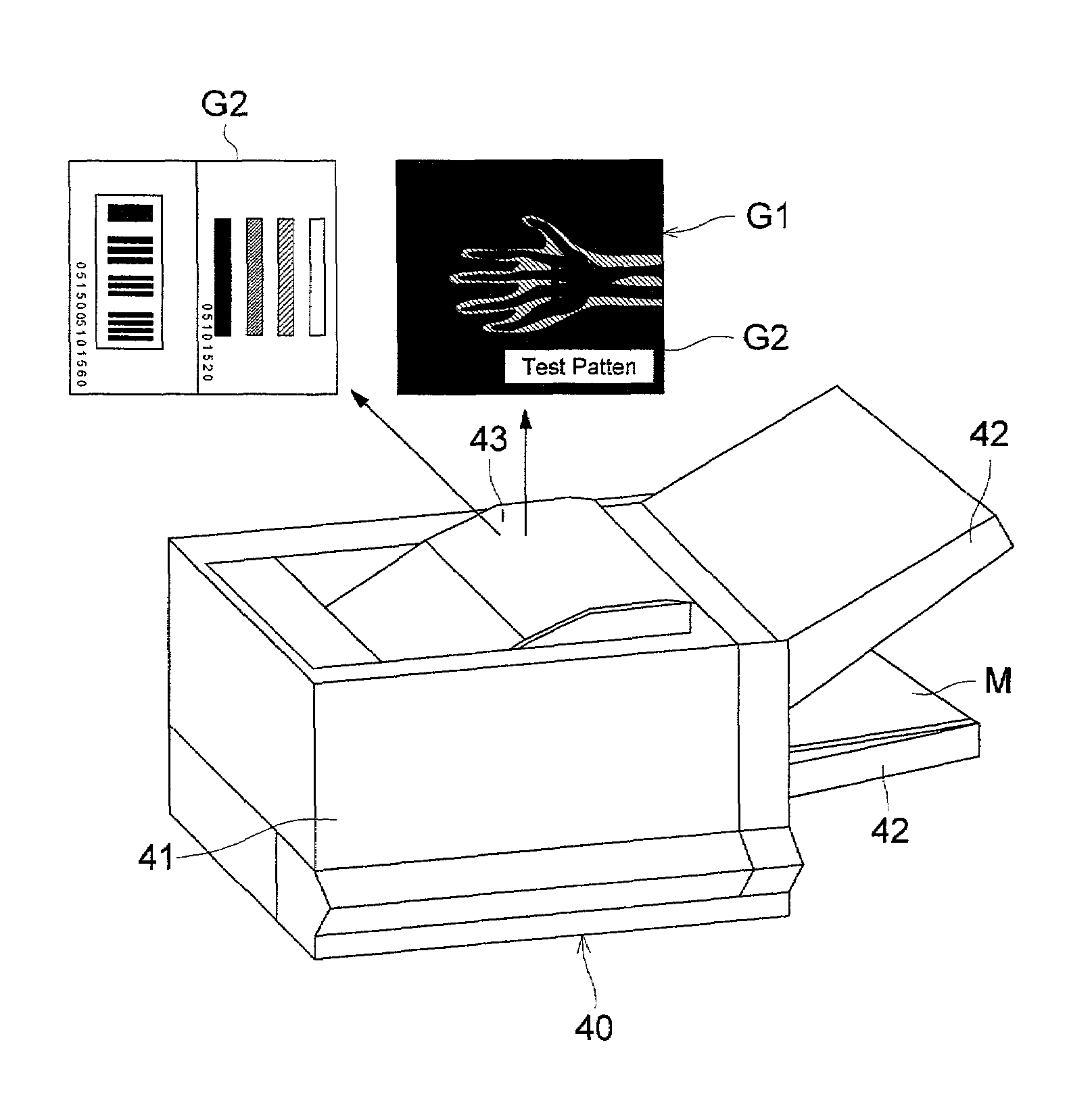
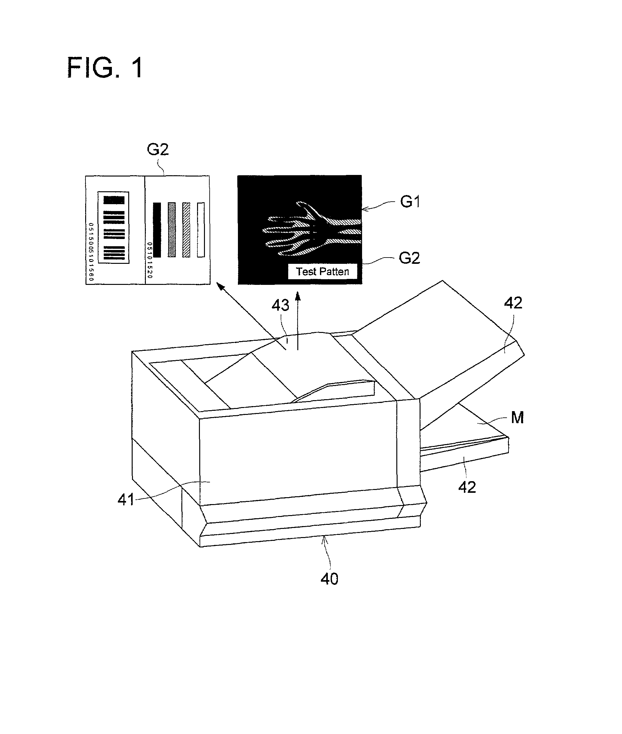
[0204]The invention will be explained as follows, referring to the embodiment. FIG. 1 is a perspective view of ink jet type recording apparatus 40 representing an image forming apparatus of the present embodiment. In the ink jet type recording apparatus 40, inputted image signals are subjected to pseudo-continuous tone processing such as error diffusion or dither, and ink is stuck on a recording medium through an ink jet method based on the processed image signals, and thereby, an image having halftone, such as a medical image, can be formed. In the ink jet type recording apparatus 40, feeding tray 42 is mounted on apparatus main body 41 to be of two decks, for example, and recording medium M loaded on either one of the two decks, for example, loaded on lower feeding tray 42 is fed to the inside of the apparatus main body 41, and the recording medium M on which images G1 and G2 are formed is taken out to ejection section 43.

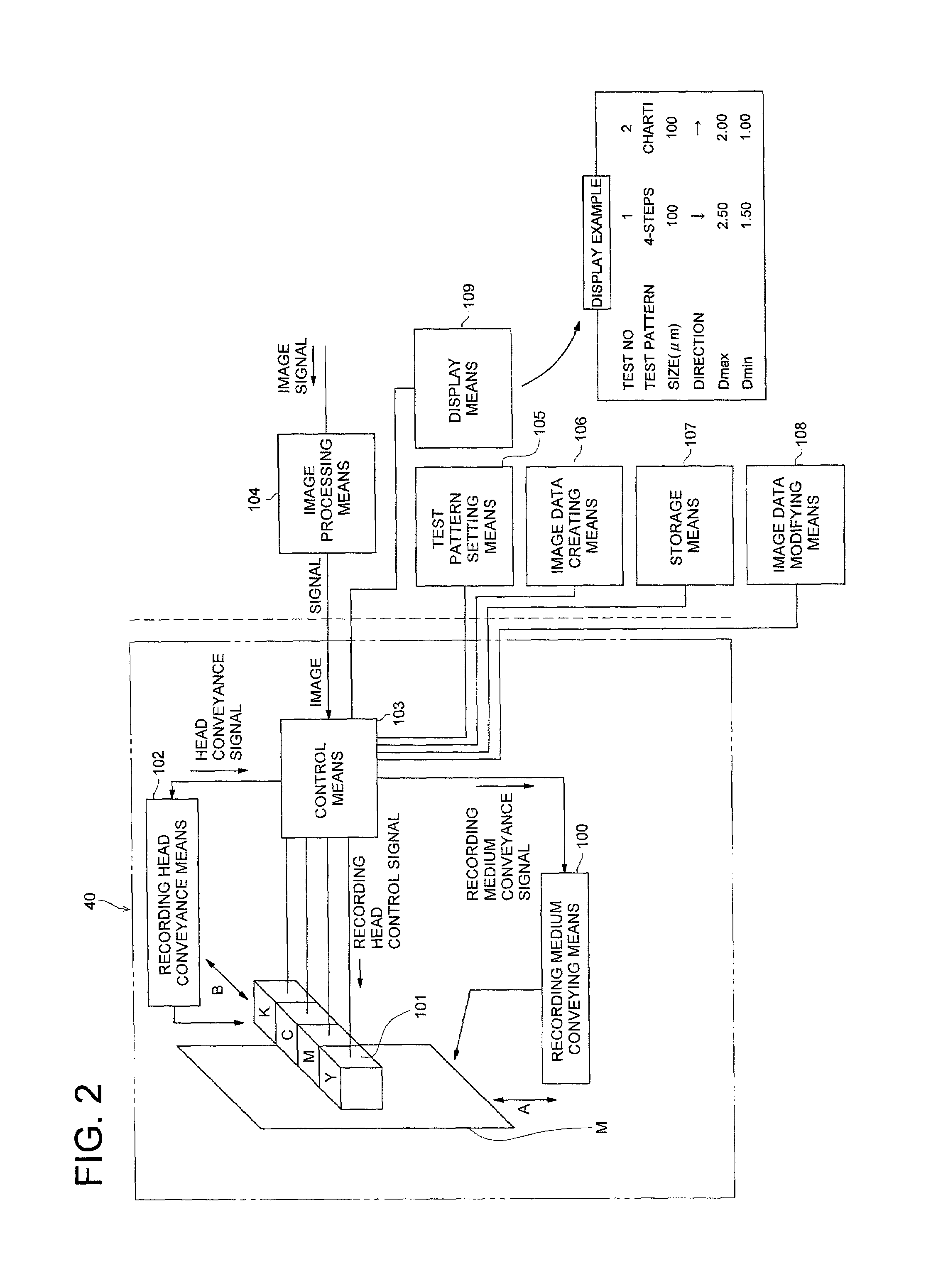
[0205]FIG. 2 is a block diagram showing a schematic structu...


PUM


Abstract

The invention concerns an image recording apparatus suitable for forming a medical image that is used for a medical diagnosis, and a test pattern for evaluating a quality of the medical image. The image recording apparatus includes a printing section to either the medical image or the test pattern on the recording medium, based on image date; a printing-condition setting section to set a printing condition for printing the test pattern; and a printing-condition displaying section to display the printing condition set by the printing-condition setting section. The printing section prints at least one of a sharpness-evaluating pattern and a granularity-evaluating pattern.

Description

BACKGROUND OF THE INVENTION[0001]The present invention relates to an image recording apparatus, and in particular, to an image recording apparatus suitable for forming a medical image that is used for diagnosis or used for reference, and to a test pattern for evaluating the same.[0002]In the medical field, radiation images have so far been formed on silver halide films to be used for diagnoses made by medical doctors. In recent years, however, technologies for processing digital images have made progress, and there has been increased the number of radiographing apparatuses (modalities) for medical use each being capable of outputting digital image data corresponding to images obtained through radiographing. If images obtained through radiographing can be stored in the form of digital image data, image processing is easy, less space is required for storage, and aging deterioration of an image is hardly caused even when the digital image data are stored for a long time, which is an ad...

Claims


Application Information

Patent Timeline
IPC IPC(8): G06F15/00B41J2/205B41J29/393H04N1/00H04N1/407
CPCB41J2/205H04N1/00002H04N1/00015H04N1/00031H04N1/00045H04N1/00053H04N1/00063H04N1/4078G03G2215/00067
Inventor YAMANO, AKIRA
Owner KONICA CORP
Learn More