
Wireless LAN communication system

a communication system and wireless technology, applied in the field of wireless lan communication system, can solve the problems of inability to automatically switch from infrastructure mode into ad-hoc mode, and the limited capacity of automatic switching of communication mod

Active Publication Date: 2007-05-22
NEC CORP
View PDF9 Cites 41 Cited by
  • Summary
  • Abstract
  • Description
  • Claims
  • Application Information

AI Technical Summary

Benefits of technology

The present invention provides a wireless LAN communication system that automatically switches between an infrastructure mode and an ad-hoc mode based on the communication status. This allows for proper communication mode selection based on the situation. The system includes a switching controller that monitors data transmitted from a source station to an access point and determines if communication in the ad-hoc mode is possible. The switching controller stores the data and selects an ad-hoc channel for communication. The system also includes an access point that stores ad-hoc network information and periodically transmits beacon signals to stations to switch between the infrastructure mode and the ad-hoc mode. The technical effects of the invention include improved communication flexibility and efficiency.

Problems solved by technology

In the conventional wireless LAN communication system, although a wireless station can automatically switch the communication mode from the ad-hoc mode into the infrastructure mode, automatic switching from the infrastructure mode into the ad-hoc mode is impossible.
That is, the capability of automatic switching of the communication mode is very limited.

Method used


Image

  • Wireless LAN communication system
  • Wireless LAN communication system
  • Wireless LAN communication system

Examples


Embodiment Construction

[0039]The present invention is described in further detail below with reference to preferred embodiments in conjunction with the accompanying drawings. Note that the drawings show only major parts relating to the present invention.

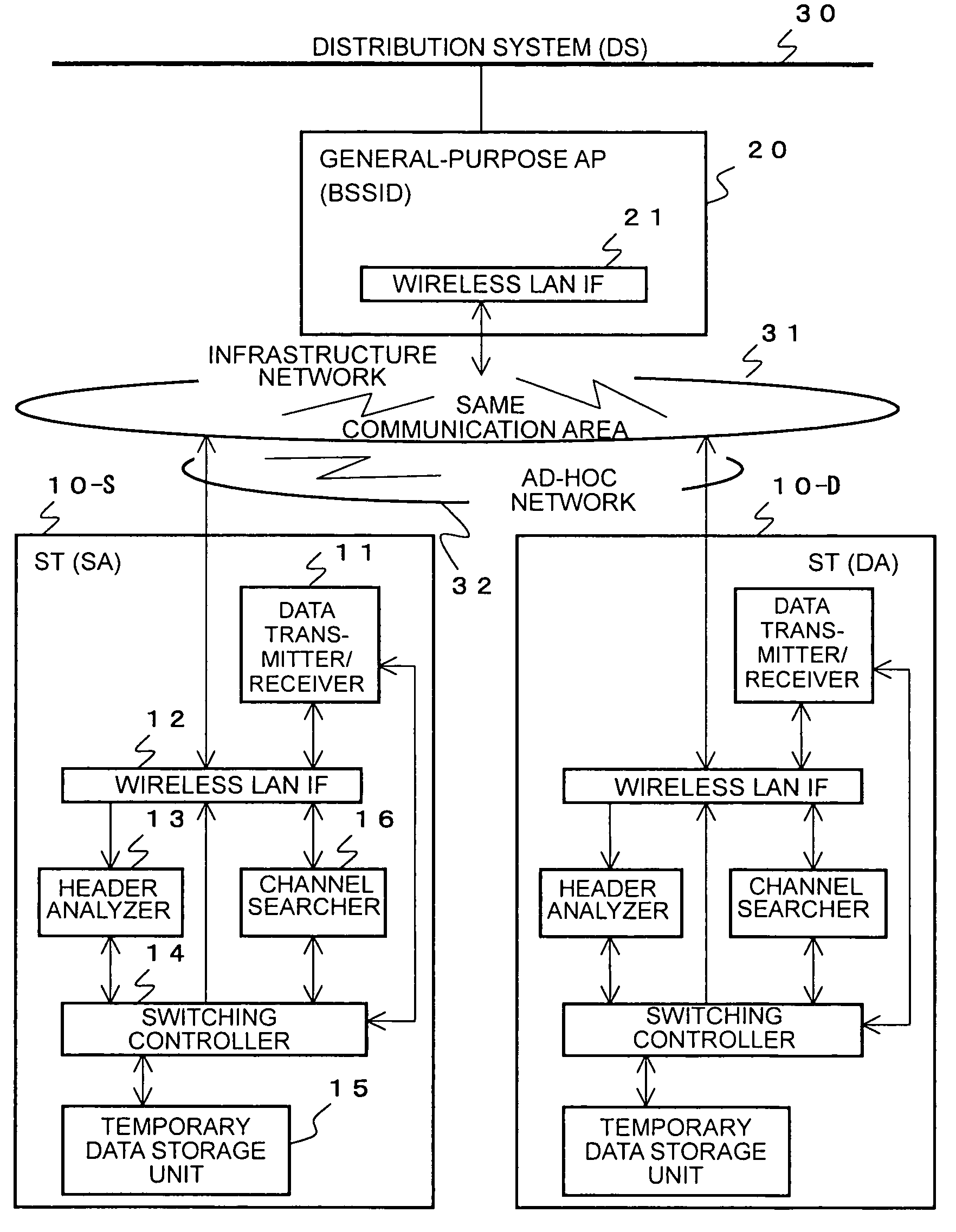
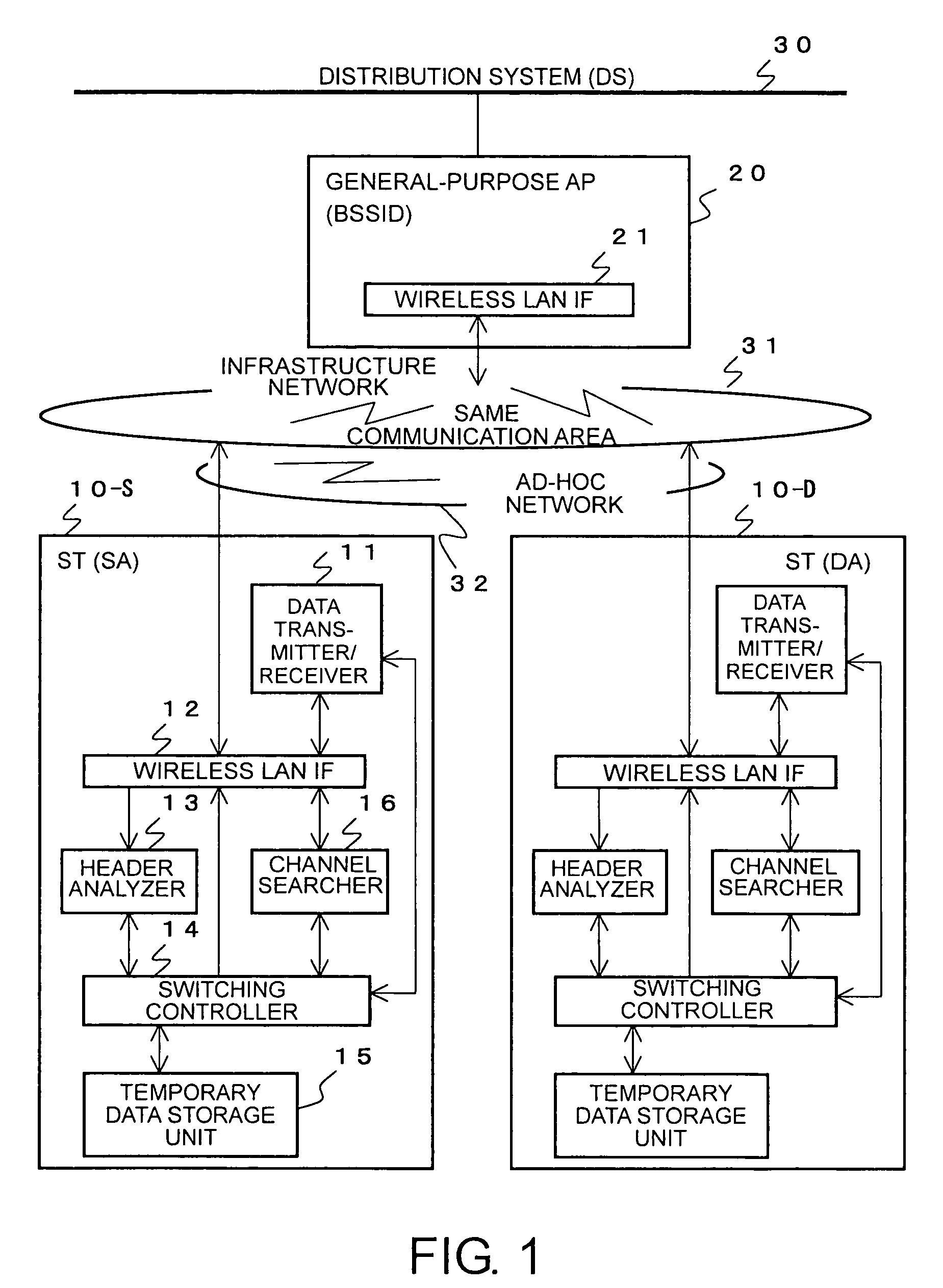
[0040]FIG. 1 is a block diagram showing a wireless LAN communication system according to an embodiment of the present invention.

[0041]In FIG. 1, shown are two stations (STs) 10 and one general-purpose access point (AP) 20 in the wireless LAN communication system. A distribution system (DS)) 30 is a wired LAN such as Ethernet (registered trademark). Although only one general-purpose AP 20 is shown in. FIG. 1, the wireless LAN communication system generally includes a plurality of general-purpose APs 20 forming an extended service set (ESS).

[0042]An infrastructure network 31 and an ad-hoc network 32 form a wireless LAN. The general-purpose AP 20 can communicate with STs 10 in a communication area provided by the infrastructure network 31. The ad-hoc network ...


PUM


Abstract

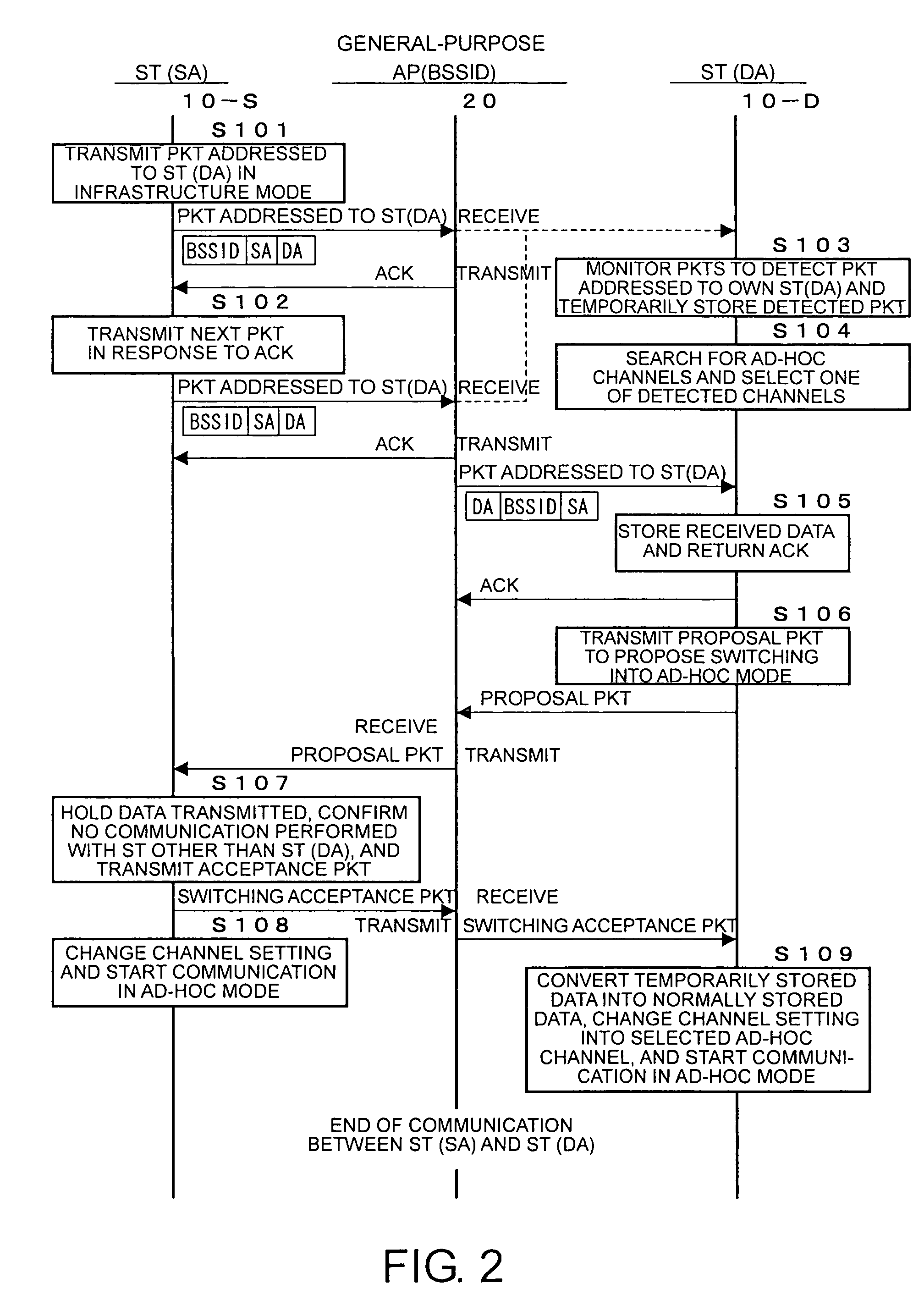
In a wireless LAN communication system, a communication mode is automatically switched between an infrastructure mode and an ad-hoc mode. Communication between two stations is started in the infrastructure mode. Packets transmitted in an infrastructure network are monitors to detect a packet transmitted to an access point and addressed, as a final destination, to one's own station or a destination station. If such a packet is detected, it is determined that a transmitting or source station is in a state that allows an ad-hoc communication. A channel searcher of the access point searches for available channels of an ad-hoc network. A switching controller selects one of the available channels and transmits information indicating the selected channel to the source and destination stations. In response to receiving the information indicating the selected channel, the source and destination stations starts direct communication using the selected channel of the ad-hoc network. The selection of the channel may be performed by a station. Associated data may be stored in a temporary data storage unit.

Description

BACKGROUND OF THE INVENTION[0001]1. Field of the Invention[0002]The present invention relates to a wireless LAN communication system having an infrastructure mode and an ad-hoc mode. Wherein, in the infrastructure mode, each station communicates with another station via an access point, while, in the ad-hoc mode, direct communication is performed between two stations located near each other. More particularly, the present invention relates to a wireless LAN communication system as follows. In wireless LAN communication system, when one station is capable of communicating directly with another station without needing an access point, communication is performed in the ad-hoc mode. And when communication in the ad-hoc mode is impossible, communication is performed in the infrastructure mode. In such cases, the communication mode should be automatically switched between the ad-hoc mode and the infrastructure mode depending on the status.[0003]2. Description of the Related Art[0004]Wirel...

Claims


Application Information

Patent Timeline
Patent Type & Authority Patents(United States)
IPC IPC(8): H04Q7/24H04L12/28H04L12/46H04L29/06H04W74/02H04W84/12H04W84/18H04W88/08
CPCH04W74/02H04L69/22H04W84/12H04W84/18
Inventor HORI, MASATOKOBAYASHI, YOSHIKAZU
Owner NEC CORP
Learn More