Bearing assembly

Inactive Publication Date: 2007-05-29
SCHAEFFLER TECH AG & CO KG
View PDF32 Cites 33 Cited by
  • Summary
  • Abstract
  • Description
  • Claims
  • Application Information

AI Technical Summary

Benefits of technology

[0026]It is advantageous if the axially flex

Problems solved by technology

However, internal combustion engines, as well as other components such as transmissions, generate noises, which might generally be perceived as a nuisance.
In the case of steplessly adjustable transmissions, noise

Method used


Image

  • Bearing assembly
  • Bearing assembly
  • Bearing assembly

Examples


Embodiment Construction

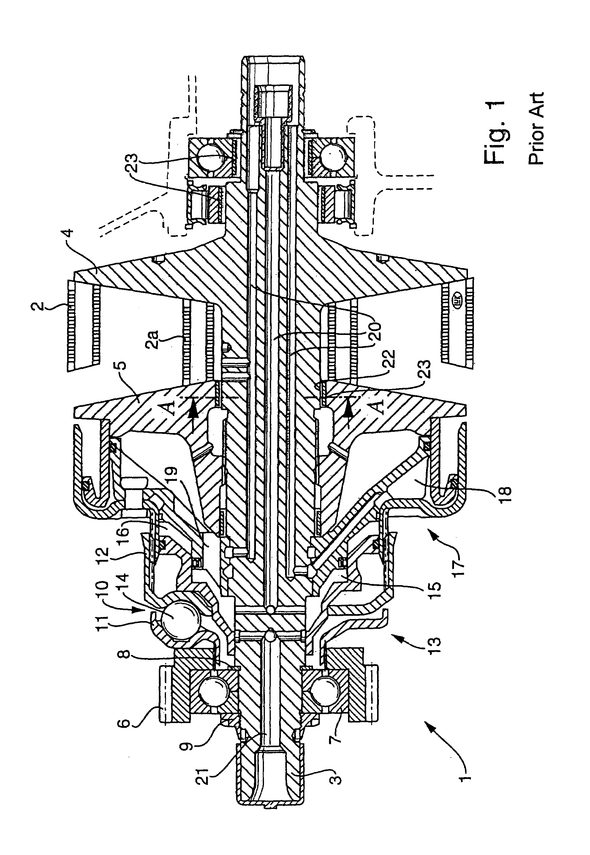
[0045]FIG. 1 shows only part of a belt-driven, conical pulley transmission, i.e., the part of the belt-driven, conical pulley transmission 1 at the driving or input end that is driven by a drive motor, such as an internal combustion engine. In the case of a fully implemented belt-driven, conical pulley transmission, a complementary output side part of the continuously variable transmission is arranged with the input end part, both parts being interconnected by a drive belt, such as a plate link chain 2, for torque transmission. The belt-driven, conical pulley transmission 1 has an input side shaft 3, which, in the illustrated embodiment is integral with a fixed conical disk 4.

[0046]This axially fixed conical disk 4 is located in the axial direction of shaft 3 and opposite from and adjacent to an axially displaceable conical disc 5.

[0047]In the FIG. 1 embodiment the plate link chain 2 at the input end conical disk pair 4, 5 is shown in a radially outward position, which is a result o...


PUM


Abstract

A bearing assembly including a bearing having an outer bearing ring and an inner bearing ring. The outer bearing ring is axially received in a bearing-receiving recess that includes a substantially cylindrical inner wall. An element that is radially flexible is located between at least one of the outer bearing ring and the inner wall of the recess, and the inner bearing ring and a rotatable member that is rotatably carried in the bearing assembly. The flexible element includes at least one annular element that is undulated in the radial direction, or is provided with projections. Flexible elements can also be disposed against a side surface of the bearing ring for damping axial vibrations.

Description

CROSS REFERENCE TO RELATED APPLICATIONS[0001]The present application is a continuation of International Application No. PCT / DE01 / 03736, filed on Sep. 28, 2001.BACKGROUND OF THE INVENTION[0002]1. Field of the Invention[0003]The invention relates to a bearing assembly for a rotatable shaft, particularly of a motor vehicle transmission. Furthermore, the invention pertains to a spring, particularly for use in a bearing assembly, and a transmission for use in an above-named bearing assembly.[0004]2. Description of the Related Art[0005]The comfort requirements for motor vehicles are generally very high, particularly with respect to acoustics. Especially in the case of high-end motor vehicles, the driver and the passengers don't want to hear background noises arising from the operation of the motor vehicle's components during vehicle operation. However, internal combustion engines, as well as other components such as transmissions, generate noises, which might generally be perceived as a n...

Claims


Application Information

Patent Timeline
IPC IPC(8): F16F1/18F16C27/06F16C19/06F16C27/04F16C35/073F16C35/077F16H57/02
CPCF16C27/04F16C35/073F16C35/077F16C19/06F16C2226/60F16C2361/65
Inventor BAUER, CHRISTIANLINNENBRUGGER, ANDREWODTKE, HANS-WALTER
Owner SCHAEFFLER TECH AG & CO KG
Why Eureka
Try Eureka