Method for orthogonal analyte stacking/injection systems in electrophoresis

an electrophoresis and analyte technology, applied in the direction of liquid/fluent solid measurement, fluid pressure measurement, peptide, etc., can solve the problem that the high-resolution capabilities of capillary electrophoresis cannot be preserved, and many analytical detection systems are inadequate to detect analyte, etc. problem, to achieve the effect of faster and higher sensitivity injection mode, high resolution

Inactive Publication Date: 2007-05-29
UNIV OF VIRGINIA ALUMNI PATENTS FOUND
View PDF1 Cites 24 Cited by
  • Summary
  • Abstract
  • Description
  • Claims
  • Application Information

AI Technical Summary

Benefits of technology

[0017]Another advantage of the present invention method is that it allows the loading of multiple-capillary volumes of sample for the first time.
[0018]Moreover, another advantage of the present invention method is that it provides a higher resolution for injection of large sample plugs in capillary electrophoresis, providing a faster and higher sensitivity injection mode in capillary electrokinetic chromatography.
[0019]Previously, long sample plugs could be injected into a capillary by pressure, with post-injection stacking of analytes occurring due to electrophoretic phenomena. However, the present invention provides a method and system where stacking can be initiated with injection, rather than post-injection. The present invention further provides electrokinetic injection of neutral analytes with concomitant stacking of neutral analytes can be initiated at the commencement of injection. See Palmer, J.; Burgi, D. S.; Munro, N. J.; Landers, J. P., “Electrokinetic Injection for Stacking Neutral Analytes in Capillary and Microchip Electrophoresis”, Anal. Chem. 2001, 73,725–731.
[0020]Further still, the present invention method provides an electrokinetic injection of neutral analytes by electroosmotic flow in the presence of an orthogonal stacking system, i.e., an anionic electrokinetic vector in the separation buffer, constitutes an orthogonal analyte stacking / injection system (OAS / IS). The requisite conditions are simply that the electrokinetic vector in the separation buffer has a mobility opposite that of the analyte injection force, and that a suitable stacking boundary is formed between the injected sample and the electrokinetic vector in the separation buffer. As will be discussed later, an extensive list of conditions for OAS / IS is included in Tables 1–6. With properly instituted OAS / IS conditions, it is actually possible to inject sample volumes (plugs) that exceed that of the entire capillary. A schematic of this concept is shown in FIG. 1.

Problems solved by technology

With analyte concentrations below parts per million (ppm), many analytical detection systems are inadequate to detect the analyte.
However, because of the small radial dimension of a capillary, it is difficult to detect short injected plug lengths of low-concentration analytes using standard optical detection set-ups (e.g., UV-VIS absorbance detection).
As a result of the fact that separation columns are of a finite length, injection plug length is limited, in practical terms, to the millimeter range—beyond this, the high-resolution capabilities of capillary electrophoresis cannot be preserved.
However, this problem has been circumvented by protocols that invoke mechanisms that narrow, or stack, much longer analyte zones into sample plugs.
Another drawback associated with large sample plug pressure injections is that the effective capillary length available for separation is reduced, having undesirable effects on the ability to resolve analytes.
While longer capillaries might be used to overcome this problem, the 30 kV limit associated with most CE instrumentation does not allow for the same high fields (800–1000 volts / cm) typically needed for rapid, high-resolution analyses to be applied.
In addition, longer capillary lengths are not conducive with translating stacking methods from the traditional capillary format to the microchip format.

Method used


Image

  • Method for orthogonal analyte stacking/injection systems in electrophoresis
  • Method for orthogonal analyte stacking/injection systems in electrophoresis
  • Method for orthogonal analyte stacking/injection systems in electrophoresis

Examples


example no.1

EXAMPLE NO. 1

Mode for Carrying Out the Experiment—Example No. 1

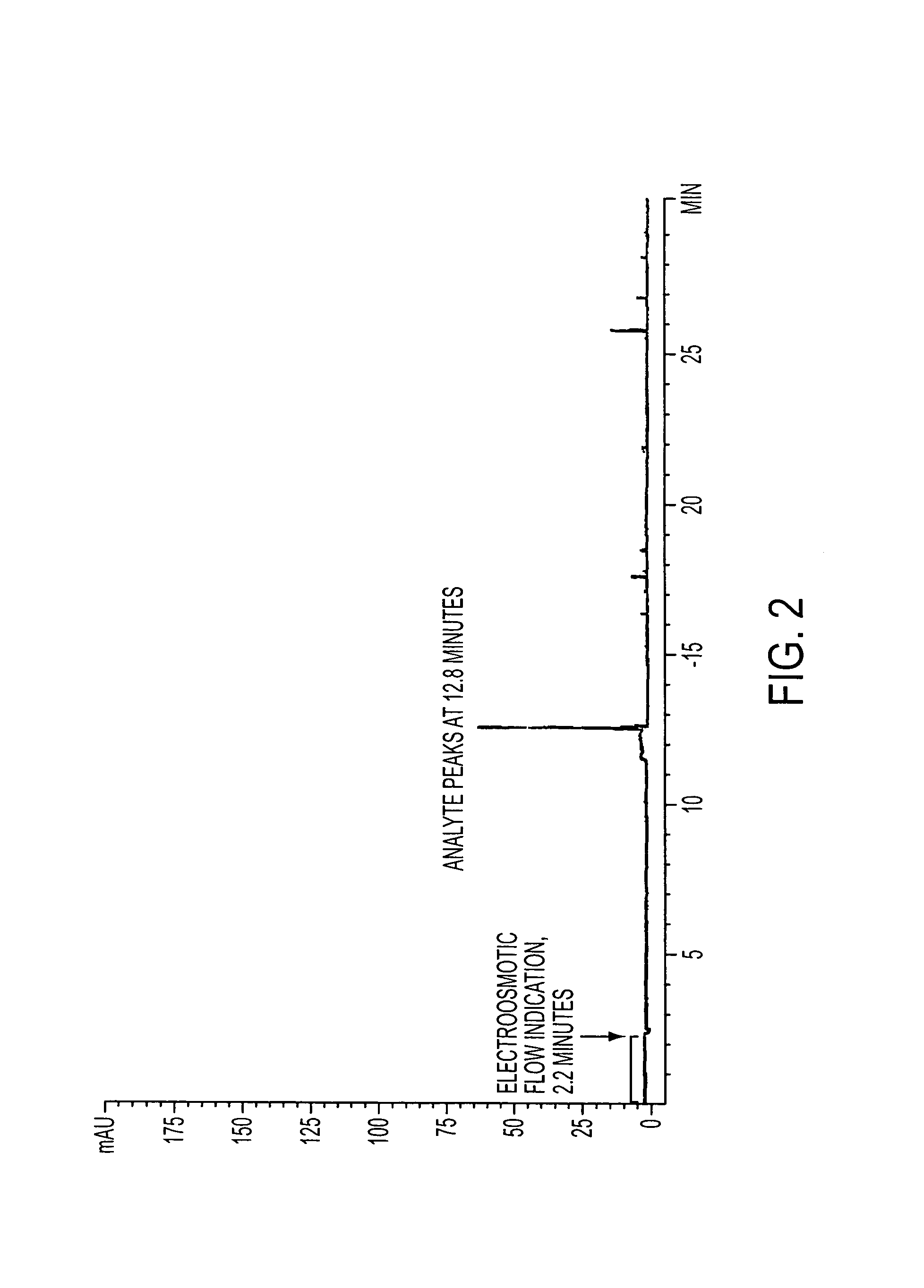
[0097]With regards to the materials, HPLC-grade water (Fisher Company, St. Louis, Mo.) was used for all separation buffers and sample matrixes. Sodium tetraborate, sodium hydroxide, sodium chloride, and punctilious ethanol were obtained from Sigma Company (St. Louis, Mo.). Cholic acid, sodium salt hydrate, was obtained from Aldrich Chemical Company (Milwaukee, Wis.). Corticosteroids were obtained from Steraloids, Inc. (Newport, R.I.). BODIPY (4,4-difluoro-5,7-dimethyl-4-bora-3a,4a-diaza-s-indacene-3-propanol) was obtained from Molecular Probes Company(Eugene, Oreg.), and sodium fluorescein was obtained from Acros Company, New Jersey. Sodium dodecyl sulfate was obtained from Bio-Rad Laboratories (Hercules, Calif.).

[0098]With respect to the capillary electrophoresis, experiments with corticosteroid analytes were conducted with a Hewlett Packard HP 3D-CE instrument interfaced with a Hewlett Packard Kayak XA computer with HP...

example no.2

EXAMPLE NO. 2

Conclusions

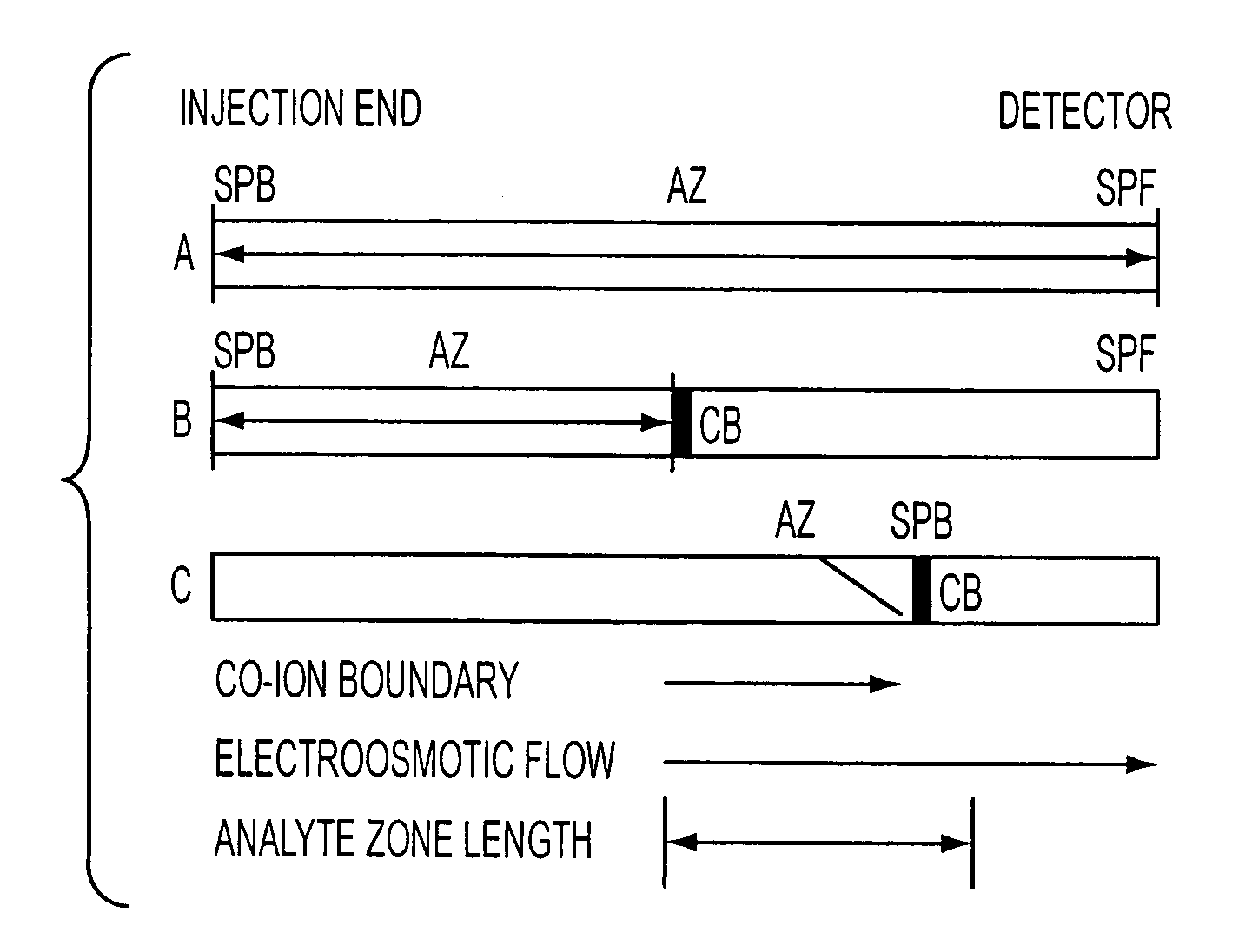
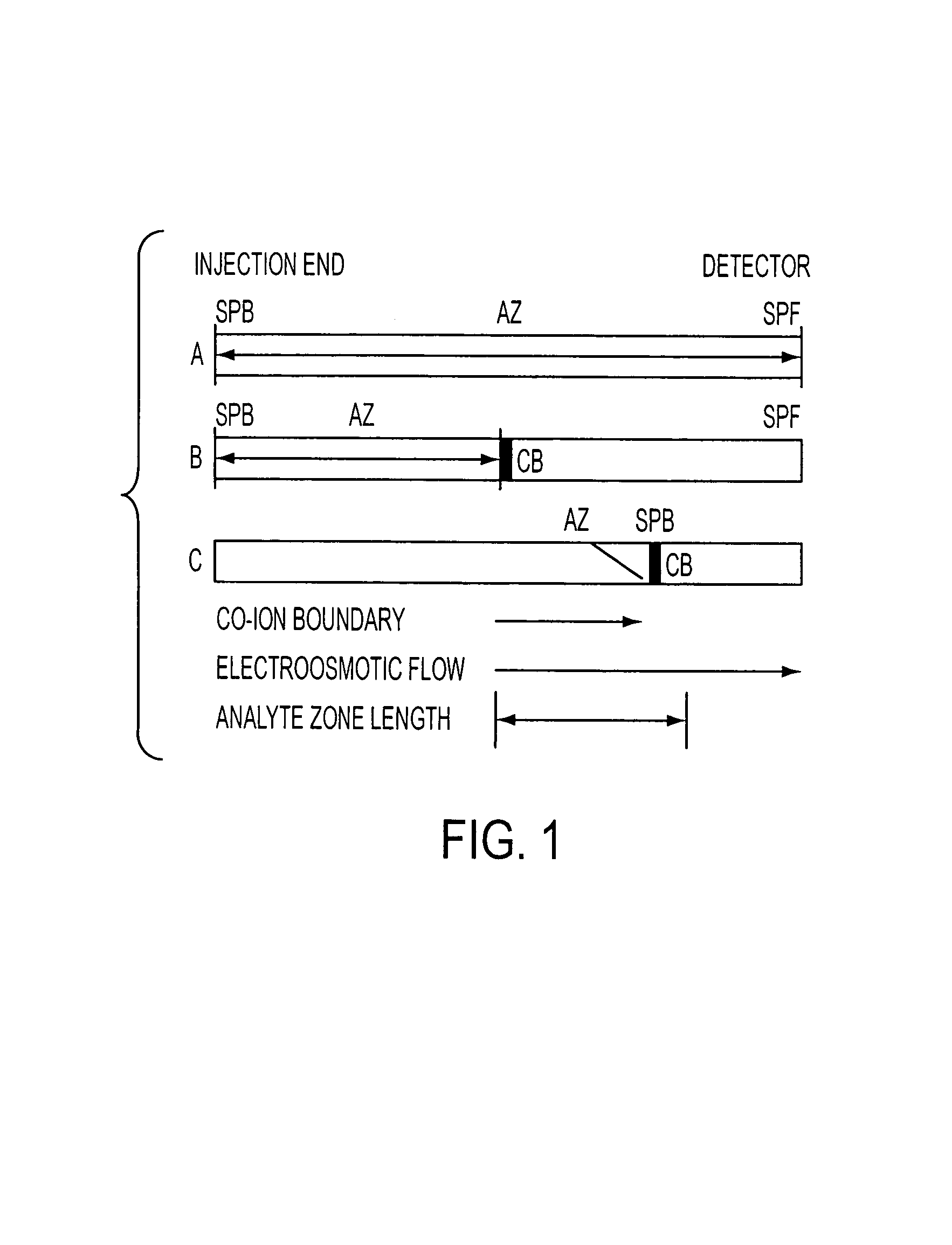
[0130]Extreme attenuation of analyte zones is obtained by extended electrokinetic stacking injection in EKC. Separation buffer parameters were investigated to allow extended injection plug lengths with continuous conductivity sample matrixes. As analytes are injected by electroosmotic flow into the separation buffer, each analyte exhibits a decrease in velocity due to the interaction with the micelles in the separation buffer. To determine maximum-length injections, the velocity of each analyte / electrokinetic vector complex must be considered. Equations have been introduced to determine the maximum injection length per individual analyte / micelle complexes.

[0131]A simple relationship exists between the velocity of the electrokinetic injection vector and the resultant velocity of analytes that encounter an electrokinetic vector that imparts a mobility that is opposite that of the injection vector. This relationship determines the maximum injectable plug length....


PUM

PropertyMeasurementUnit
electric fieldaaaaaaaaaa
atmospheric pressureaaaaaaaaaa

Abstract

In the present capillary electrokinetic chromatograpy method, analytes are injected by electroosmotic flow directly from a sample matrix into a separation buffer containing an electrokinetic vector with an opposite mobility. Analytes can now be injected at the velocity of electroosmotic flow, but are retained at the interface of the sample matrix-co-ion and separation buffer micelle zones as analyte / micelle complexes. Manipulation of the injecting force and opposing stacking force allow greatly increased length or volume of injection. Concentrations of the micelle, methanol, and borate in the separation buffer were provided to increase maximum injection length of neutral analytes. Reducing the analyte velocity in the separation buffer without substantially decreasing the velocity of the analyte during injection from the sample vial allowed greatly extended sample plug injection lengths. It is further enabled to inject sample solvent volumes equivalent to about twenty times the effective capillary volume. Equations and algorithms describing the injection process and maximum injection lengths for this mode of stacking in electrokinetic capillary chromatography are introduced. Use of the present method provides for maximum electrokinetic stacking injection for a wide variety of analytes and separation systems.

Description

RELATED APPLICATIONS[0001]This application is a national stage filing of International Application No. PCT / US01 / 43259, filed Nov. 19, 2001, which claims benefit under 35 U.S.C. Section 119(e) from U.S. Provisional Application Ser. No. 60 / 249,611, filed on Nov. 17, 2000, entitled “Orthogonal Analyte Stacking / Injection Systems in Capillary Electrophoresis,” the entire disclosures of which are hereby incorporated by reference herein in their entirety. The present application is a continuation-in-part of U.S. patent application Ser. No. 09 / 418,659, filed Oct. 15, 1999, entitled “Method and Injection and Stacking of Analytes in High-conductivity Samples,” the entire disclosure of which is hereby incorporated by reference herein, and which is now U.S. Pat. No. 6,569,305B1.FIELD OF INVENTION[0002]This invention relates to an improved method and system for stacking analytes in electrophoresis, and more particularly an orthogonal analyte stacking / injection system that allows the loading of v...

Claims


Application Information

Patent Timeline
Patent Type & Authority Patents(United States)
IPC IPC(8): G01N27/453G01N27/447
CPCG01N27/44743
Inventor LANDERS, JAMES P.PALMER, JAMES F.
Owner UNIV OF VIRGINIA ALUMNI PATENTS FOUND
Why Eureka
Try Eureka