Drill bit assembly with an indenting member

a technology of indenting member and drill bit, which is applied in the direction of drilling pipes, directional drilling, borehole/well accessories, etc., can solve the problems of drilling bit damage, drill bit damage, and drill bit replacement in the field is often costly and time-consuming, and achieves the effect of increasing the drilling rate of penetration

Inactive Publication Date: 2007-06-05
SCHLUMBERGER TECH CORP
View PDF81 Cites 40 Cited by
  • Summary
  • Abstract
  • Description
  • Claims
  • Application Information

AI Technical Summary

Problems solved by technology

Often drill bits are subjected to harsh conditions when drilling below the earth's surface.
Replacing damaged drill bits in the field is often costly and time consuming since the entire downhole tool string must typically be removed from the borehole before the drill bit can be reached.
Bit whirl in hard formations may result in damage to the drill bit and reduce penetration rates.
Further loading too much weight on the drill bit when drilling through a hard formation may exceed the bit's capabilities and also result in damage.
Too often unexpected hard formations are encountered suddenly and damage to the drill bit occurs before the weight on the drill bit may be adjusted.
A low whirling frequency accompanied by a high acceleration magnitude based on empirically established values is associated with destructive vibration of the drilling component.

Method used


Image

  • Drill bit assembly with an indenting member
  • Drill bit assembly with an indenting member
  • Drill bit assembly with an indenting member

Examples


Embodiment Construction

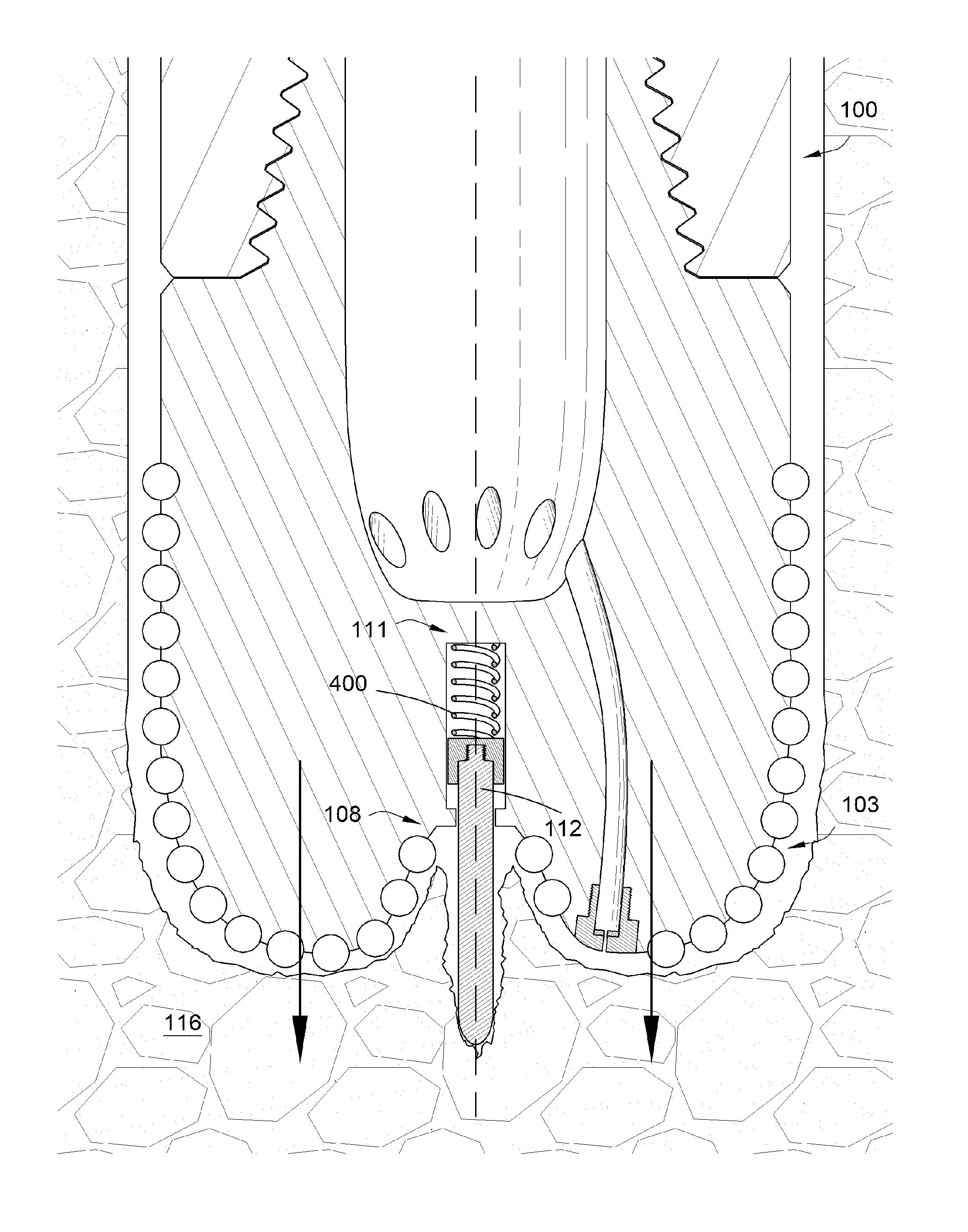
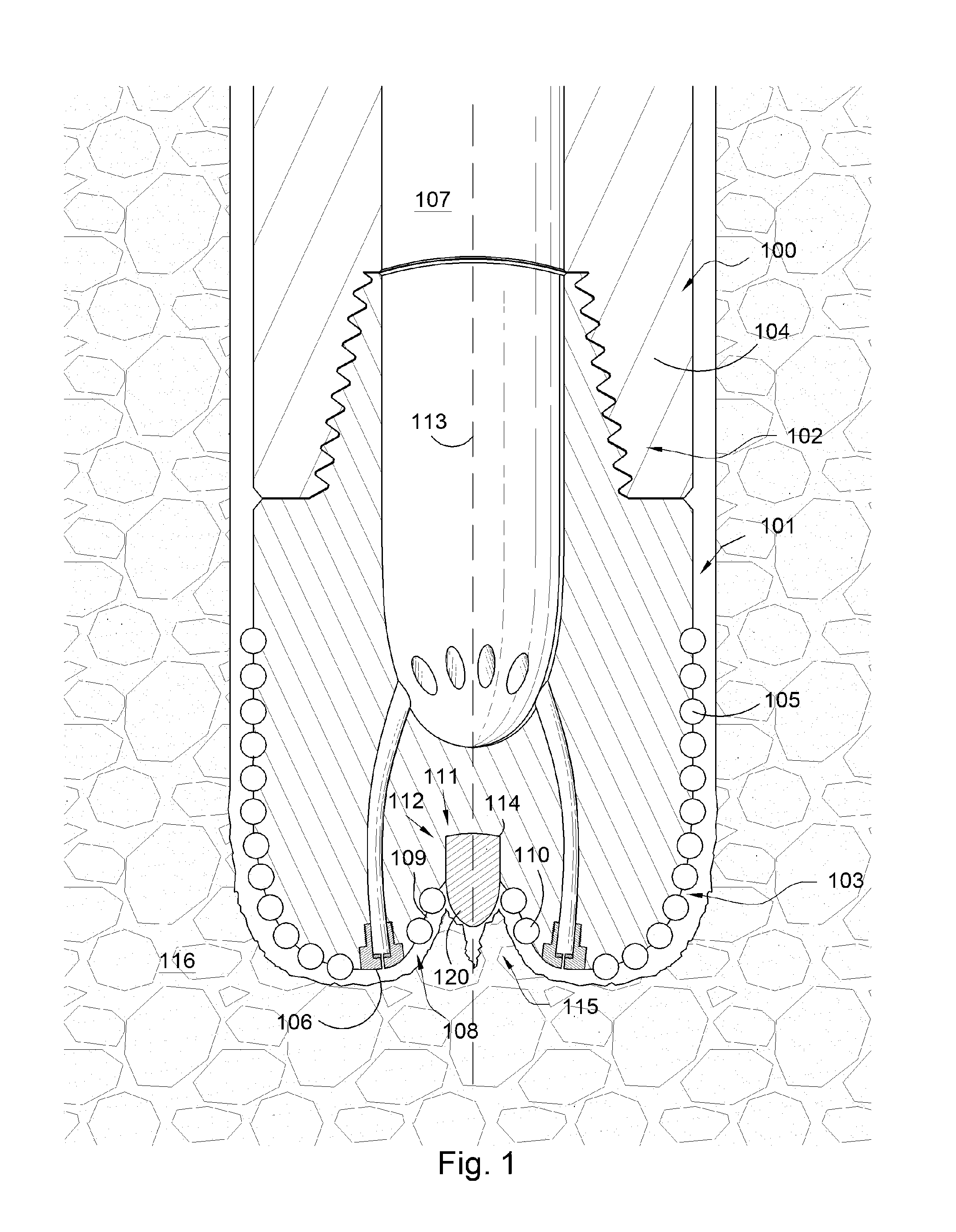
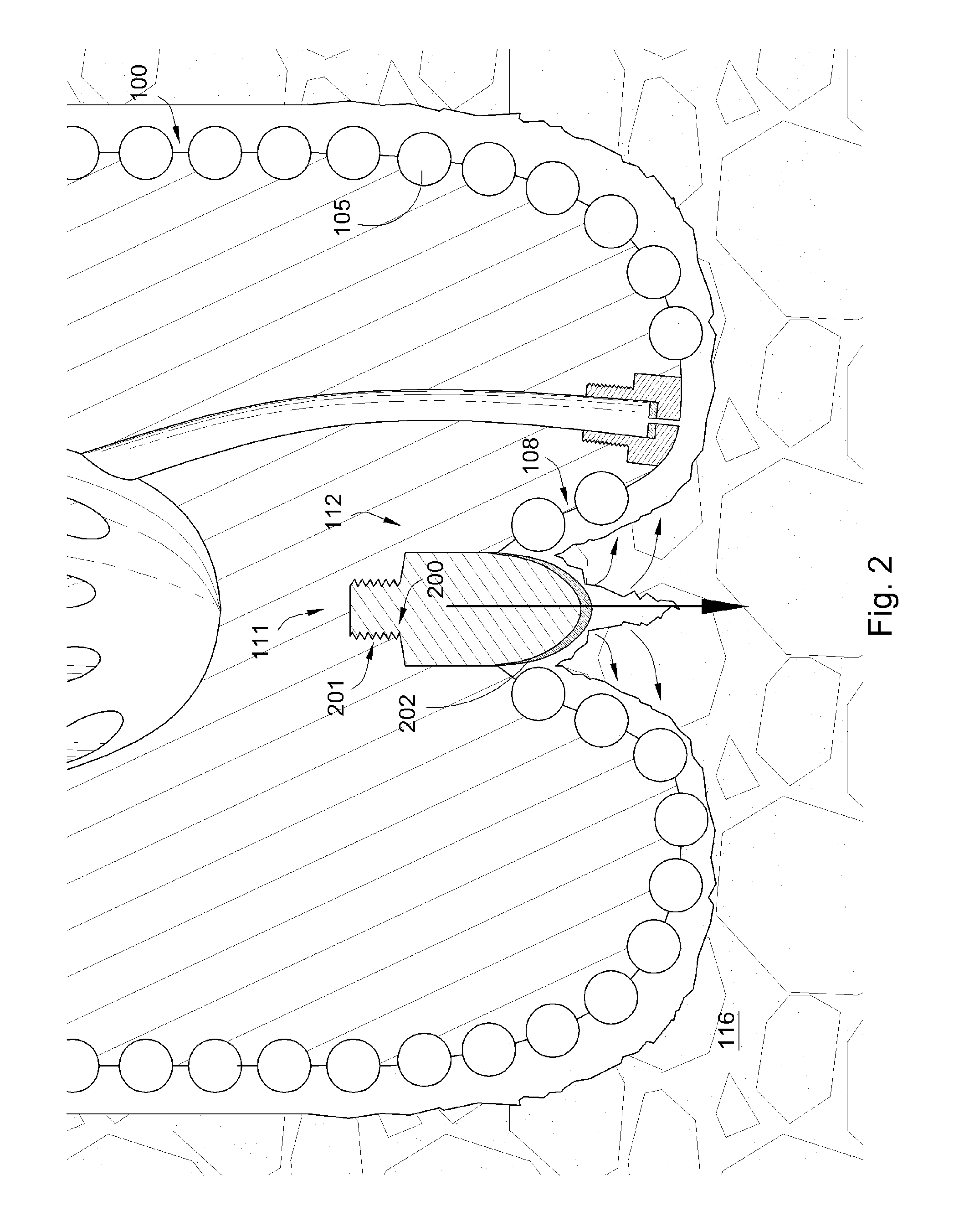
[0031]FIG. 1 is a cross sectional diagram of an embodiment of a drill bit assembly 100. The assembly 100 comprises a body portion 101 intermediate a shank portion 102 and a working portion 103. The shank portion 102 is connected to a component 104 of a downhole tool string. The working portion 103 comprises a plurality of cutting elements 105, preferably comprising polycrystalline diamond. A least one nozzle 106 is attached to the working portion 103 and is in communication with a bore 107 of the downhole tool string. The working portion 103 also comprises a recess 108. The side wall 109 of the recess 108 comprises at least one cutting element 110, as shown in FIG. 1, the cutting element is a shearing element. Preferably the cutting element 110 is also comprises polycrystalline diamond. In some embodiments of the invention, the shearing cutting 110 and / or the plurality of cutting elements 105 may comprise another superhard material such as diamond or cubic boron nitride. In a closed...


PUM


Abstract

In one aspect of the invention a drill bit assembly has a body portion intermediate a shank portion and a working portion. The working portion has a recess with a side wall which is substantially coaxial with the shank portion. At least one cutting element is attached to the side wall and an indenting member is disposed within the closed end. In another aspect of the invention a method includes providing a drill bit assembly with a recess formed in a working portion of the assembly. The working portion has a plurality of cutting elements and the recess has at least one cutting element. The method further has steps of cutting a formation with the plurality of cutting elements and also of penetrating a conical profile of the formation which is formed by the recess.

Description

CROSS REFERENCE TO RELATED APPLICATIONS[0001]This patent application is a continuation-in-part of U.S. patent application Ser. No. 11 / 306,022 filed on Dec. 14, 2005 now U.S. Pat. No. 7,198,119, entitled Hydraulic Drill Bit Assembly. U.S. patent application Ser. No. 11 / 306,022 is a continuation-in-part of U.S. patent application Ser. No. 11 / 164,391 filed on Nov. 21, 2005, which is entitled Drill Bit Assembly. Both of these applications are herein incorporated by reference in their entirety.BACKGROUND OF THE INVENTION[0002]This invention relates to drill bits, specifically drill bit assemblies for use in oil, gas and geothermal drilling. Often drill bits are subjected to harsh conditions when drilling below the earth's surface. Replacing damaged drill bits in the field is often costly and time consuming since the entire downhole tool string must typically be removed from the borehole before the drill bit can be reached. Bit whirl in hard formations may result in damage to the drill bi...

Claims


Application Information

Patent Timeline
Patent Type & Authority Patents(United States)
IPC IPC(8): E21B10/26E21B10/48
CPCE21B10/43E21B10/62F24T2010/53Y02E10/10E21B10/633
Inventor HALL
Owner SCHLUMBERGER TECH CORP
Why Eureka
Try Eureka