RFID device tester and method

a technology of radio frequency identification and tester, which is applied in the direction of burglar alarm mechanical actuation, burglar alarm by hand-portable object removal, instruments, etc., can solve the problems of difficult to test a single rfid device and the need to test the operation of such devices

Inactive Publication Date: 2007-06-05
AVERY DENNISON CORP
View PDF62 Cites 107 Cited by
  • Summary
  • Abstract
  • Description
  • Claims
  • Application Information

AI Technical Summary

Problems solved by technology

One difficulty associated with RFID devices is the need to test operation of such devices as part of the manufacturing or fabrication process.
When such methods are applied to testing closely-spaced RFID devices, it is difficult to test a single RFID device, since the RF field interacts with several devices simultaneously, and the various RFID devices may interact with one another.

Method used


Image

  • RFID device tester and method
  • RFID device tester and method
  • RFID device tester and method

Examples


Embodiment Construction

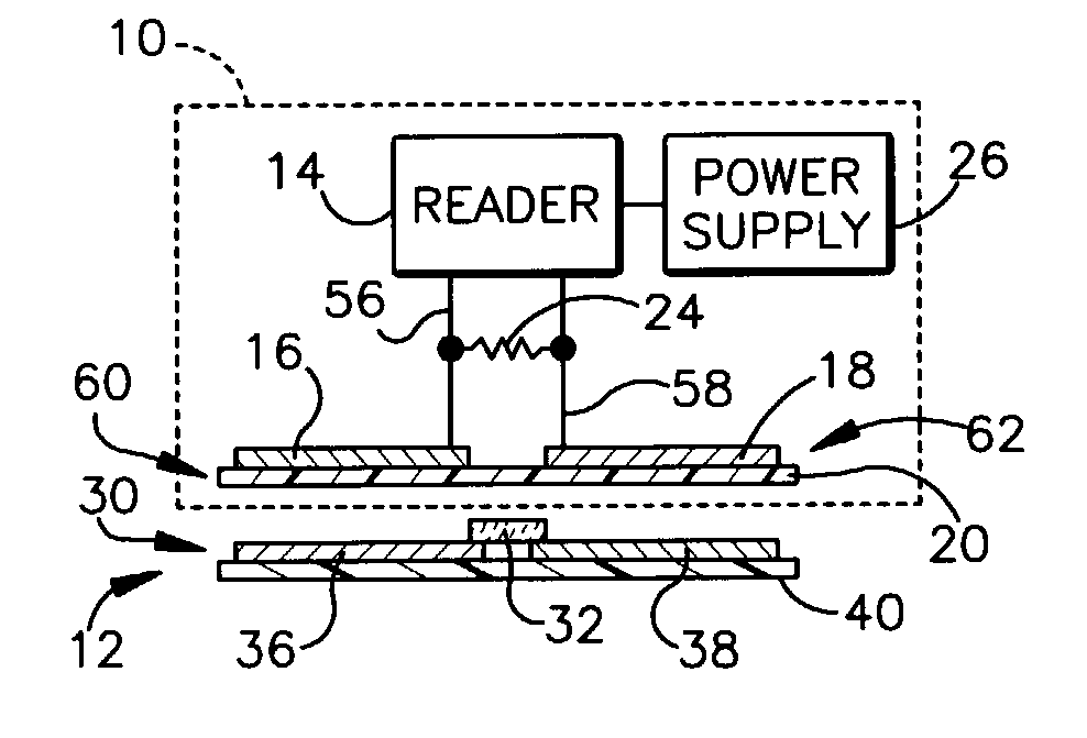
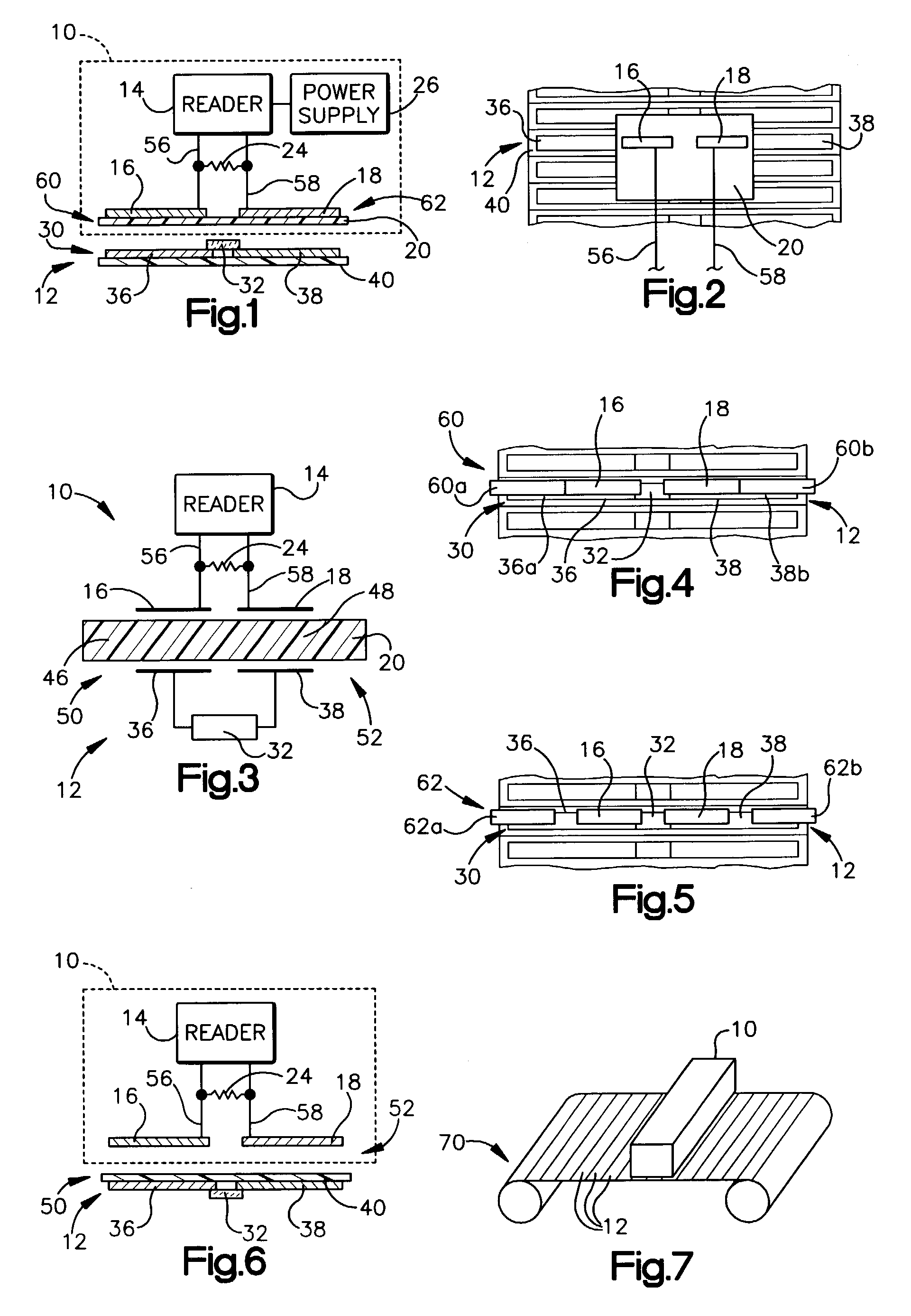
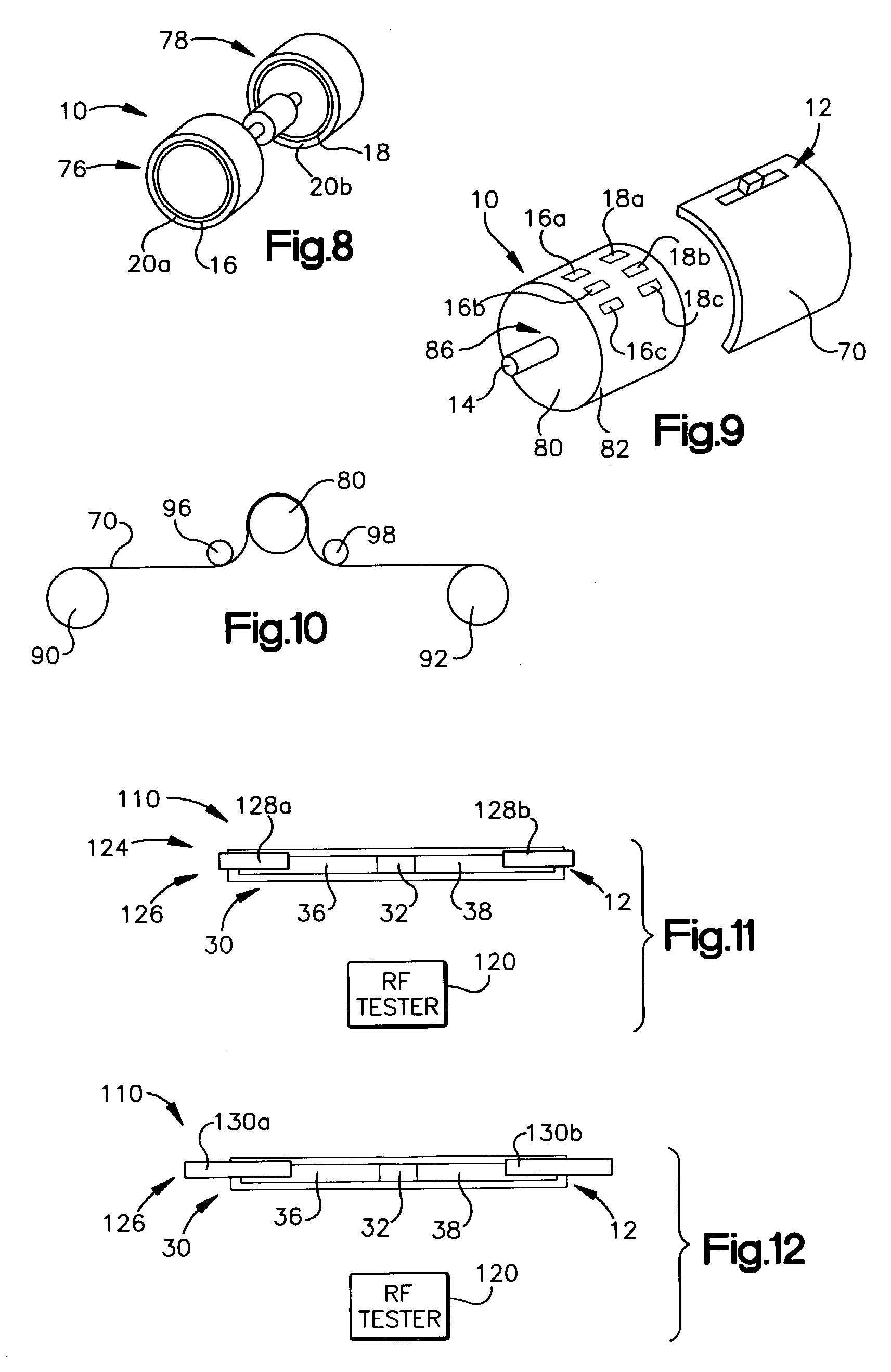
[0033]An RFID device tester includes coupling elements for capacitively coupling a reader to an RFID device to be tested. The reader may power the RFID device by sending an outgoing signal, such as an outgoing AC power signal, which may be rectified and / or reflected by the RFID device, if the RFID device is operating properly. The outgoing signal may have a frequency that is different from the resonant frequency of an antenna of the RFID device. A reader in the RFID device tester detects the reflected and / or transmitted signal to confirm proper operation of the RFID device. The RFID device tester may be used as part of a roll-to-roll process, to individually test RFID devices on a roll of material. By utilizing short-range capacitive coupling, difficulties caused by simultaneous activation of multiple RFID devices may be reduced or avoided.

[0034]Referring initially to FIGS. 1 and 2, illustrated is an RFID device tester 10 for testing or otherwise reading an RFID device 12. The teste...


PUM

PropertyMeasurementUnit
frequencyaaaaaaaaaa
frequencyaaaaaaaaaa
separation distanceaaaaaaaaaa

Abstract

An RFID device tester includes coupling elements for capacitively coupling a reader to an RFID device to be tested. The reader may power the RFID device by sending an outgoing signal, such as an outgoing AC power signal, which may be rectified and / or reflected by the RFID device, if the RFID device is operating properly. The outgoing signal may have a frequency that is different from the resonant frequency of an antenna of the RFID device. A reader in the RFID device tester detects the reflected and / or transmitted signal to confirm proper operation of the RFID device. The RFID device tester may be used as part of a roll-to-roll process, to individually test RFID devices on a roll of material. By utilizing short-range capacitive coupling, difficulties caused by simultaneous activation of multiple RFID devices may be reduced or avoided.

Description

BACKGROUND OF THE INVENTION[0001]1. Field of the Invention[0002]This invention relates to the field of radio frequency identification (RFID) tag and label detection systems, and to methods of detecting RFID tags and labels.[0003]2. Description of the Related Art[0004]Radio frequency identification (RFID) tags and labels (collectively referred to herein as “devices”) are widely used to associate an object with an identification code. RFID devices generally have a combination of antennas and analog and / or digital electronics, which may include for example communications electronics, data memory, and control logic. For example, RFID tags are used in conjunction with security-locks in cars, for access control to buildings, and for tracking inventory and parcels. Some examples of RFID tags and labels appear in U.S. Pat. Nos. 6,107,920, 6,206,292, and 6,262,292, all of which are hereby incorporated by reference in their entireties.[0005]As noted above, RFID devices are generally categoriz...

Claims


Application Information

Patent Timeline
Patent Type & Authority Patents(United States)
IPC IPC(8): G06K19/06G06K7/00
CPCG06K7/0008G06K7/10465G06K7/0095Y10T29/49004
Inventor FORSTER, IAN J.
Owner AVERY DENNISON CORP
Why Eureka
Try Eureka