Spray array apparatus

a technology of array apparatus and spray tube, which is applied in the direction of lighting and heating apparatus, launching weapons, combustion types, etc., can solve the problems of inability to cover the full range of test envelopes in tunnels and environmental chambers, and inability to predict the complex nature of ice shape formation in three dimensional flow conditions

Inactive Publication Date: 2007-06-05
THE UNITED STATES OF AMERICA AS REPRESENTED BY THE SECRETARY OF THE NAVY
View PDF11 Cites 28 Cited by
  • Summary
  • Abstract
  • Description
  • Claims
  • Application Information

AI Technical Summary

Benefits of technology

[0006]The spray apparatus includes an array of fluid conducting members each including a water channel and an air channel for respectively receiving water and warm air from a remote source. Each fluid conducting member has a rounded leading edge and a tapered trailing edge defining an airfoil. Selected ones of the fluid conducting members include one or more spray nozzles positioned at the trailing edge thereof and in fluid communication with the water and air channels. A plurality of manifold joints is provided with each having water and air passageways. Each of the manifold joints is detachably connected to a plurality of the fluid conducting members and allows fluid communication between the connected fluid conducting members.

Problems solved by technology

All of these methods however have drawbacks.
For example, computer simulation can predict ice shapes accurately only over a limited range of icing conditions and cannot predict the complex nature of ice shapes formed in three dimensional flow conditions.
Likewise, icing wind tunnels and environmental chambers cannot cover the full range of the test envelopes and there are problems with wall effects, cloud size and uniformity, turbulence, attainable airspeeds and the size of models that can be accommodated.
It is also difficult to simulate freezing rain and drizzle.
Actual in-situ testing is difficult because all types of natural icing conditions may not be available and there is a significant safety risk since the test conditions cannot be controlled.
Presently used spray arrays are limited with regard to simulating all required conditions and have difficulty in maintaining a uniform cloud with representative droplet sizes.
Often, after a flight test, examination of the array reveals many cracks, necessitating a rewelding operation.

Method used


Image

  • Spray array apparatus
  • Spray array apparatus
  • Spray array apparatus

Examples


Embodiment Construction

[0022]In the drawings, which are not necessarily to scale, like or corresponding parts are denoted by like or corresponding reference numerals.

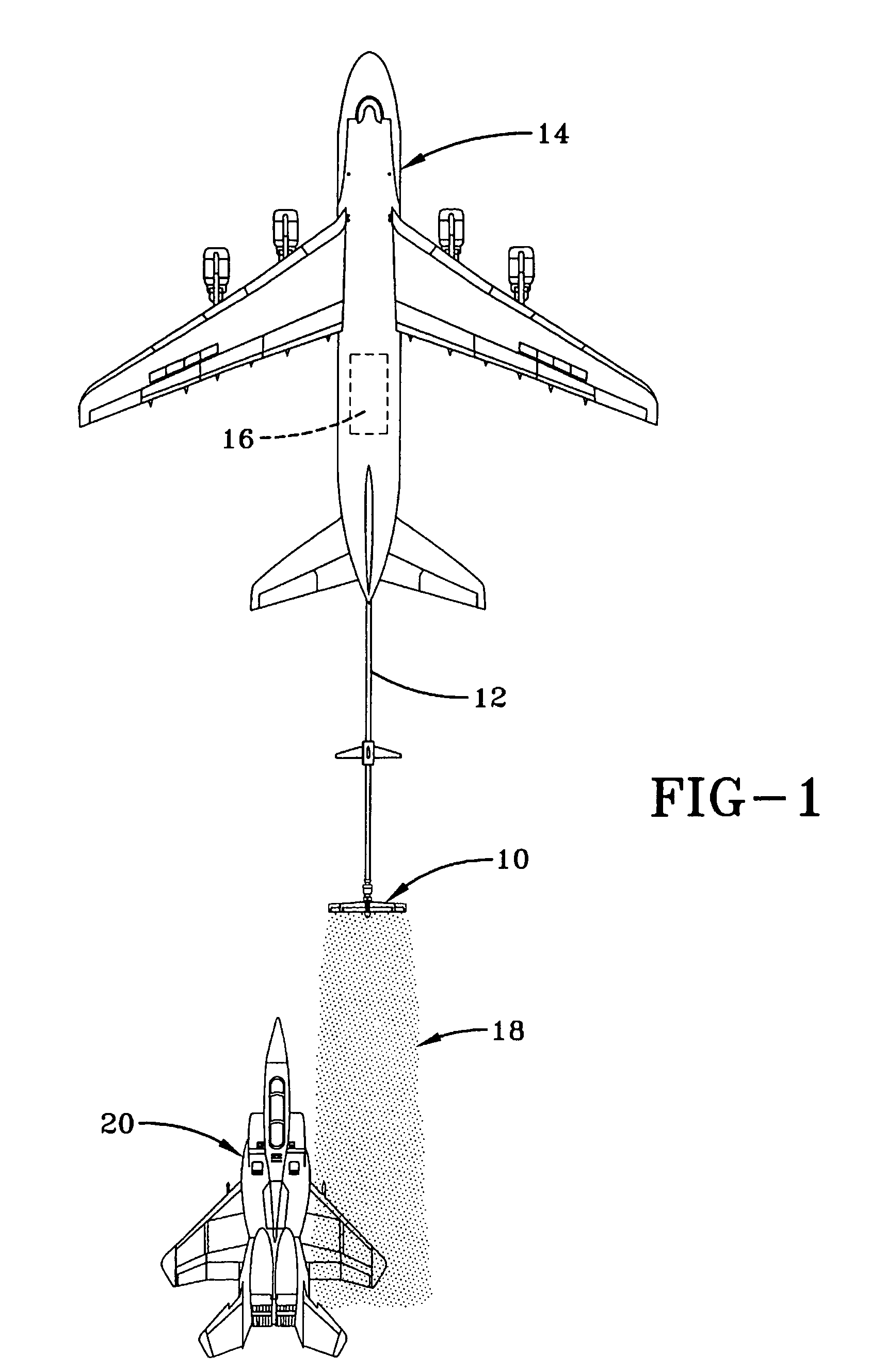
[0023]Although the apparatus of the present invention may be used in wind tunnels, or the like, it will be described, by way of example, with respect to in-situ testing under actual flight conditions. FIG. 1 illustrates the spray apparatus 10 at the end of a boom 12 of a tanker aircraft 14. Tanker aircraft 14 supplies water and warm air, typically engine bleed air, as governed by control station 16, to nozzles of the spray apparatus 10 to generate a cloud 18 having precisely controlled droplet sizes and liquid water content to meet certain standards. An aircraft 20 under test flies behind the spray apparatus 10 whereby different portions of the aircraft 20 and elements carried by it may be tested under icing as well as rain conditions.

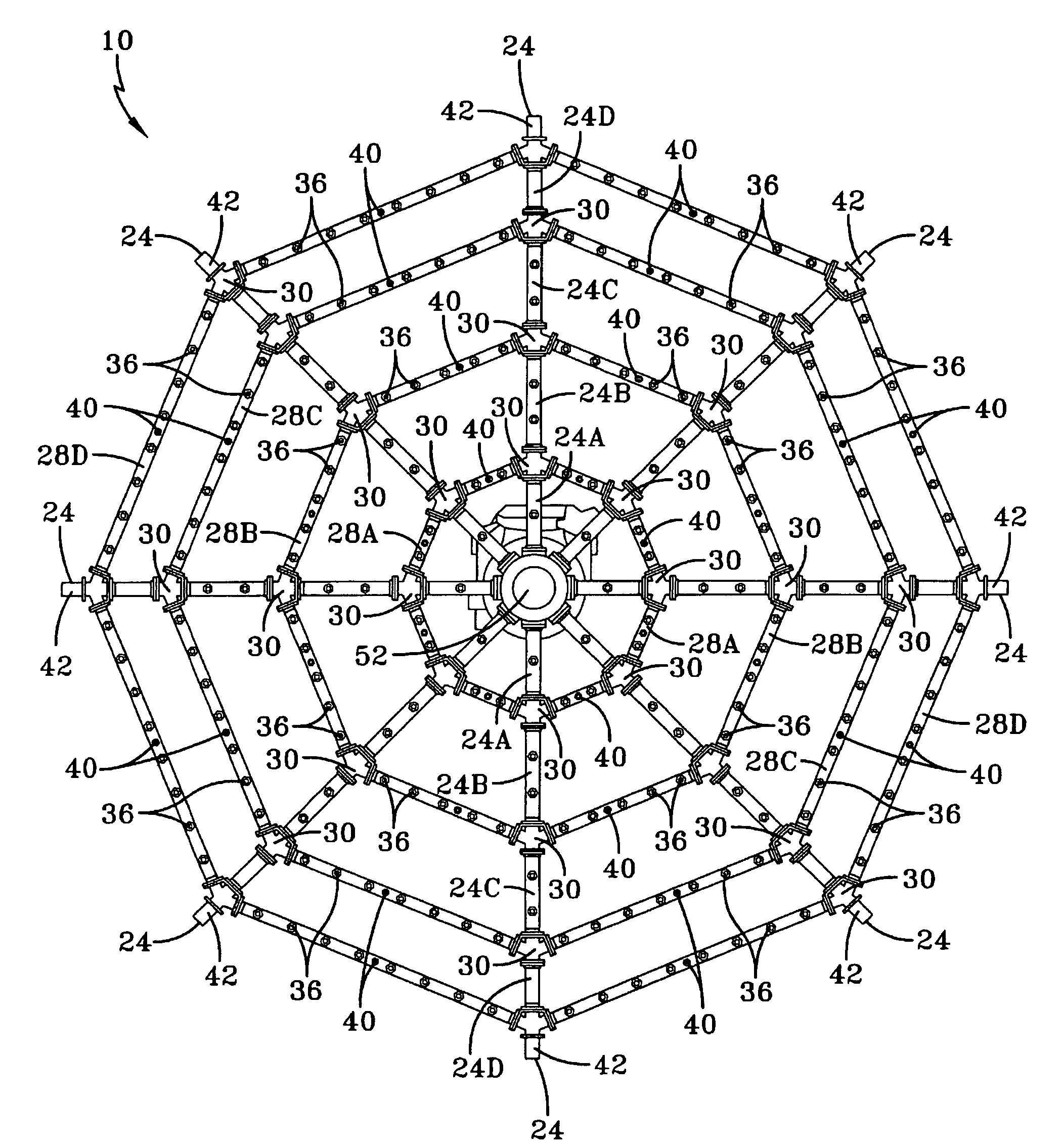
[0024]Referring now collectively to FIGS. 2 to 4, the spray apparatus 10 includes an array of fluid conductin...


PUM


Abstract

Spray array apparatus which includes a plurality of water and air carrying spoke members extending radially from a central fluid distribution assembly. The spoke members are connected to a plurality of water and air carrying strut members. The spoke members are divided into segments and the segments and strut members are detachably joined together by means of manifold joints which have water and air passageways allowing fluid communication between spoke segments and strut members. The apparatus is towed at the end of a boom of a tanker aircraft and is connected to the boom by means of a gimbal allowing two degrees of freedom to reduce bending moments and connection stresses. Selected fluid parameters are transmitted to the tanker aircraft to adjust fluid flow, if necessary.

Description

STATEMENT OF GOVERNMENT INTEREST[0001]The invention described herein may be manufactured and used by or for the Government of the United States of America for government purposes without the payment of any royalties therefor.BACKGROUND OF THE INVENTION[0002]Various methods exist for the study of ice build up on aircraft surfaces and components such as weapons systems, radomes, antennas, etc. This information is required to ensure that the aircraft and weapons systems are capable of operating within worldwide environmental conditions. These methods for the study of ice build up include analytical computer simulation, icing wind tunnels, environmental chambers and flight testing in natural icing conditions.[0003]All of these methods however have drawbacks. For example, computer simulation can predict ice shapes accurately only over a limited range of icing conditions and cannot predict the complex nature of ice shapes formed in three dimensional flow conditions. Likewise, icing wind t...

Claims


Application Information

Patent Timeline
Patent Type & Authority Patents(United States)
IPC IPC(8): B64D1/18
CPCB64D1/18B64D15/10B64F5/0018B64F5/30
Inventor FOIANINI, CURT M.HANE, THOMAS H.WOLFE, JOSEPH E.
Owner THE UNITED STATES OF AMERICA AS REPRESENTED BY THE SECRETARY OF THE NAVY
Why Eureka
Try Eureka