Tensioner with adjustable biasing force of a traction member

a technology of traction member and biasing force, which is applied in the direction of belt/chain/gearing, vehicle, and gearing, etc., can solve the problems of excessive biasing force, vibration and the initial set tension of the traction member decreasing, so as to achieve positive affecting the design

Inactive Publication Date: 2007-06-05
SCHAEFFLER TECH AG & CO KG
View PDF25 Cites 18 Cited by
  • Summary
  • Abstract
  • Description
  • Claims
  • Application Information

AI Technical Summary

Benefits of technology

[0018]As an alternative to the direct securement of the actuator to the base of the tension, it is, of course, also conceivable to provide an indirect securement of the actuator. An example includes the provision of a toggle lever having ends mounted to the machine part and the base, with the actuator secured in the area of the toggle lever. In this way, the actuator force can be multiplied, thereby positively affecting the design of the actuator or the dimension of the control element. Suitably, the toggle lever is able to impact against a stop member in one end position to thereby realize a precise position of the toggle lever and a defined position of the connected base of the tensioner.

Problems solved by technology

As a consequence of an increase in length of the traction member and an uneven rotation of the crankshaft, caused by the combustion process of the internal combustion engine, dynamic effects, such as vibrations of the traction member, are encountered.
Due to aging and wear, belts have a tendency to stretch so that the initially set tension of the traction member decreases.
Apart from the fact that the life of the traction member is adversely affected thereby, there are other negative consequences.
Because conventional tensioners are dimensioned for maximum load conditions, an excessive biasing force is applied, even though the accessories may operate at reduced load, e.g. during idling of the internal combustion engine.
In other words, the required biasing force is less than the actually applied biasing force, rendering the traction drive overly taut.
On the other hand, when the biasing force is too low at high moments, an increased slip between the traction member and the pulleys is encountered.

Method used


Image

  • Tensioner with adjustable biasing force of a traction member
  • Tensioner with adjustable biasing force of a traction member
  • Tensioner with adjustable biasing force of a traction member

Examples


Embodiment Construction

[0028]Throughout all the Figures, same or corresponding elements are generally indicated by same reference numerals. These depicted embodiments are to be understood as illustrative of the invention and not as limiting in any way. It should also be understood that the drawings are not necessarily to scale and that the embodiments are sometimes illustrated by graphic symbols, phantom lines, diagrammatic representations and fragmentary views. In certain instances, details which are not necessary for an understanding of the present invention or which render other details difficult to perceive may have been omitted.

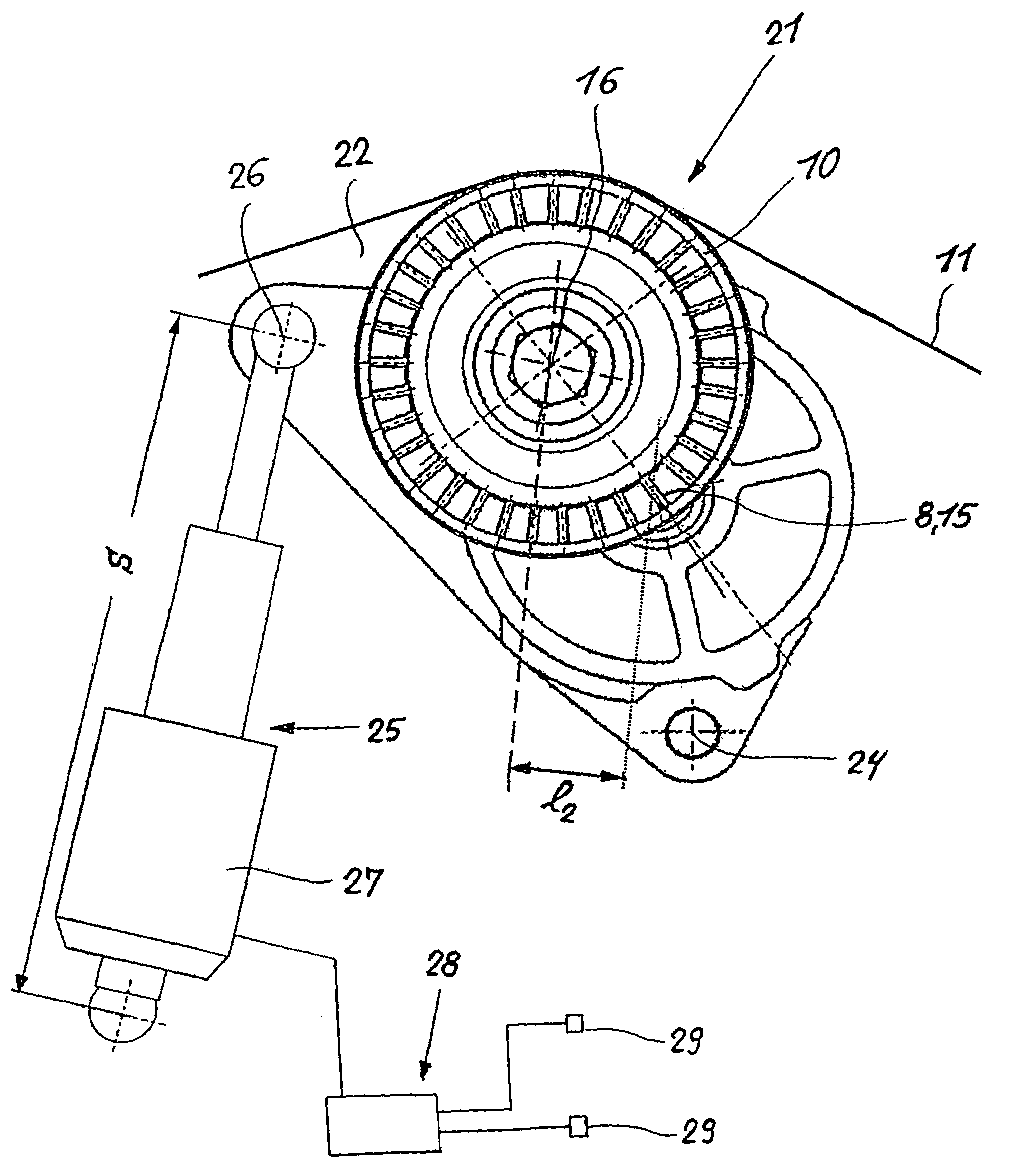
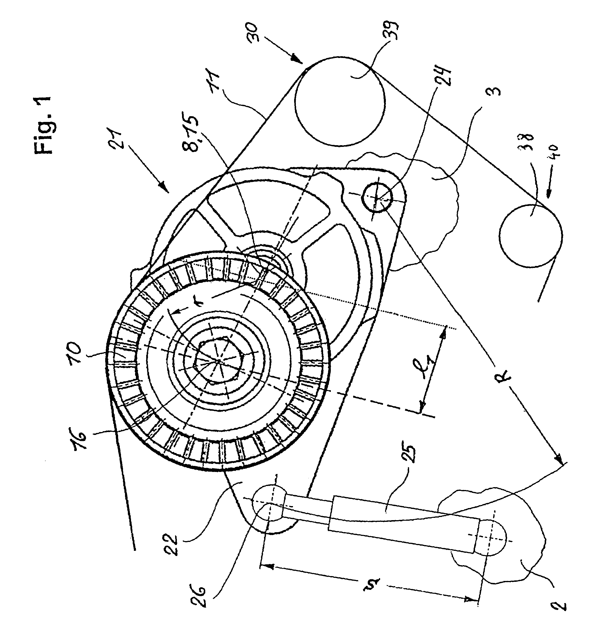
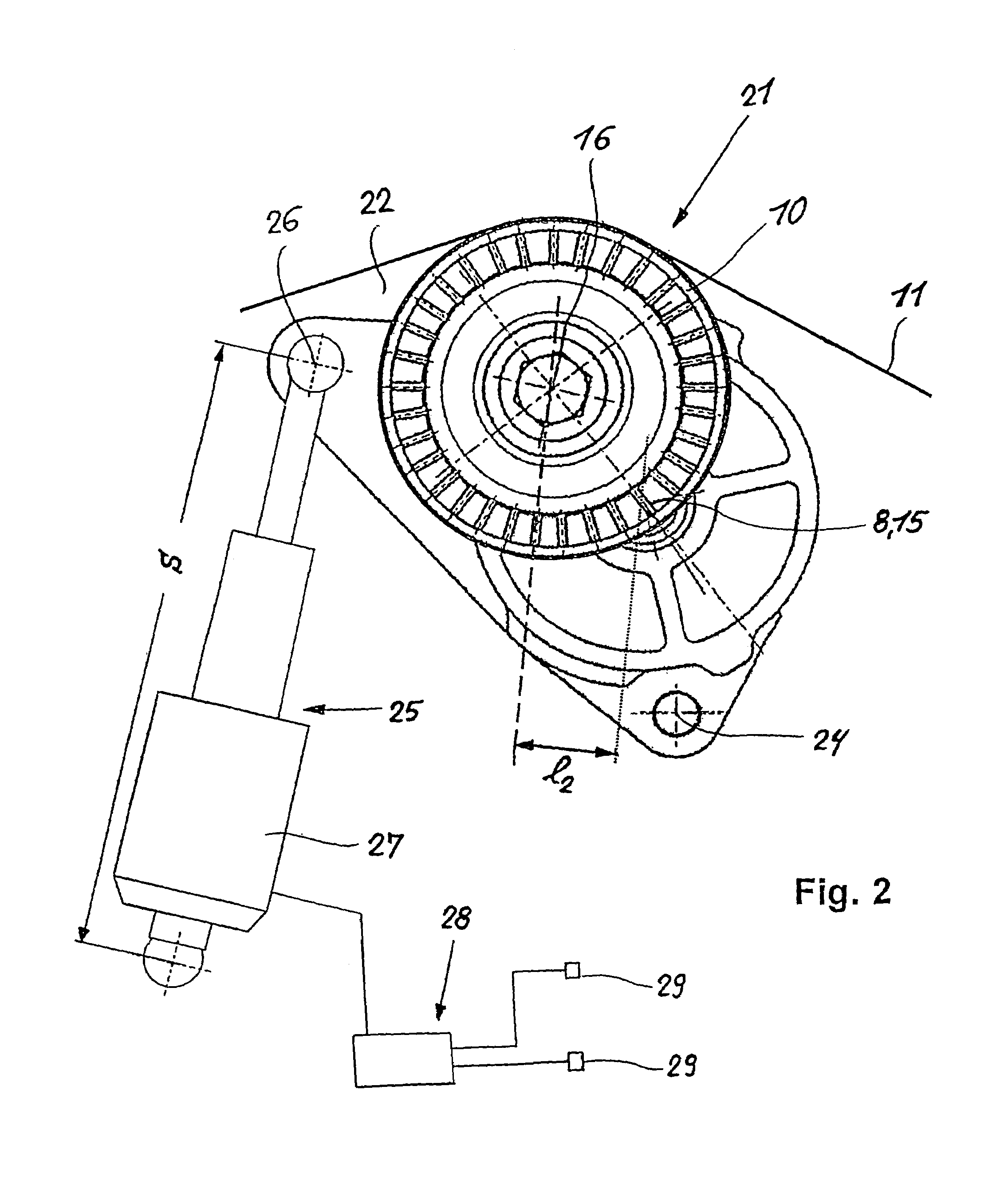
[0029]Turning now to the drawing, and first to FIG. 8, there is shown is a longitudinal section of a basic configuration of a tensioner 1 which can be complemented with the subject matter in accordance with the present invention. The tensioner 1 includes a base 22 which is fixedly secured to a machine part 3. The base 22 is formed in one piece with an axially extending cylindr...


PUM


Abstract

A tensioner for a traction member, in particular a belt of a traction drive for an internal combustion engine, includes a base constructed for rotation about a rotation axis and having a pivot arm. The pivot arm has a free end for connection of a rotatable tension roller which bears against a traction member. A spring member urges the pivot arm to seek a forced engagement of the tension roller upon the traction member. Disposed between the base and the pivot arm is a damping element for damping an adjusting movement of the pivot arm. A pivot bearing supporting one portion of the base on a machine part for rotation about the rotation axis, whereby the rotation of the base in relation to the machine part is realized by an actuator to thereby adjust a biasing force of the traction member.

Description

CROSS-REFERENCES TO RELATED APPLICATIONS[0001]This application is a continuation of prior filed copending PCT International application no. PCT / EP02 / 09378, filed Aug. 22, 2002, which designated the United States and on which priority is claimed under 35 U.S.C. §120, the disclosure of which is hereby incorporated by reference.[0002]This application claims the priority of German Patent Application, Serial No. 101 46 612.9, filed Sep. 21, 2001, pursuant to 35 U.S.C. 119(a)–(d), the disclosure of which is incorporated herein by reference.BACKGROUND OF THE INVENTION[0003]The present invention relates to a tensioner for a traction member, in particular a belt of a traction drive.[0004]Tensioners of a type involved here are used in particular in internal combustion engines for motor vehicles to ensure a slip-free drive of accessories or units that are propelled by the traction drive during start-up operation as well as generator operation, without affecting the speed pattern of the tractio...

Claims


Application Information

Patent Timeline
Patent Type & Authority Patents(United States)
IPC IPC(8): F16H7/08F16H7/12
CPCF16H7/1209F16H2007/081F16H2007/0823F16H2007/0887
Inventor KRAUS, MANFREDBOGNER, MICHAEL
Owner SCHAEFFLER TECH AG & CO KG
Why Eureka
Try Eureka