Fastening structure for add-on card

Inactive Publication Date: 2007-06-05
INVENTEC CORP
View PDF9 Cites 4 Cited by
  • Summary
  • Abstract
  • Description
  • Claims
  • Application Information

AI Technical Summary

Benefits of technology

[0009]Another objective of the present invention is to provide an add-on card fastening structure which is integrally fabricated so as to shorten and simplify the manufacturing process.
[0010]Yet another objective of the present invention is to provide an add-on card fastening structure which can be assembled and disassembled without using any tool.
[0011]A further objective of the present invention is to provide an add-on card fastening structure for reducing the manufacturing cost.
[0014]Since the add-on card fastening structure of the present invention is integrally fabricated, it solves a drawback of the aforesaid prior art, that is, the framework and the fastener have to be separately manufactured before they are assembled and thus the assembly process is complex. In other words, the present invention simplifies and shortens the assembly process.
[0015]Furthermore, both the confining portions and the stop portion disposed on the add-on card fastening structure of the present invention serve to position an add-on card on the housing of an electronic device. As result, the present invention solves a drawback of the aforesaid prior art, that is, the installing / uninstalling of an add-on card on the housing of an electronic device in a known manner requires much screwing / unscrewing and involves using an auxiliary tool. In other words, the present invention enhances ease of use, as the installation / uninstallation of an add-on card can be carried out without adopting any additional locking component or using any tool.

Problems solved by technology

However, the aforesaid method for installing the add-on card 11 in the housing 12 of the electronic device usually involves screwing / unscrewing plenty of screws 15 and using an auxiliary tool to do the assembly and disassembly work, thereby causing users much inconvenience.
Furthermore, since the framework 21 is connected to the housing 4 of the electronic device and made of a metallic material, the manufacturing cost is high.

Method used


Image

  • Fastening structure for add-on card
  • Fastening structure for add-on card
  • Fastening structure for add-on card

Examples


Embodiment Construction

[0023]The following specific embodiment is provided to illustrate the present invention. Others skilled in the art can readily gain an insight into other advantages and features of the present invention based on the contents disclosed in this specification. The present invention can also be performed or applied in accordance with other different embodiments. Various modifications and changes based on different viewpoints and applications yet still within the scope of the present invention can be made in the details of the specification.

[0024]It should be noted that the accompanying drawings are simplified schematic diagrams and only show components relating to the present invention. In practice, the shape, quantity and size of the components may be changed if necessary.

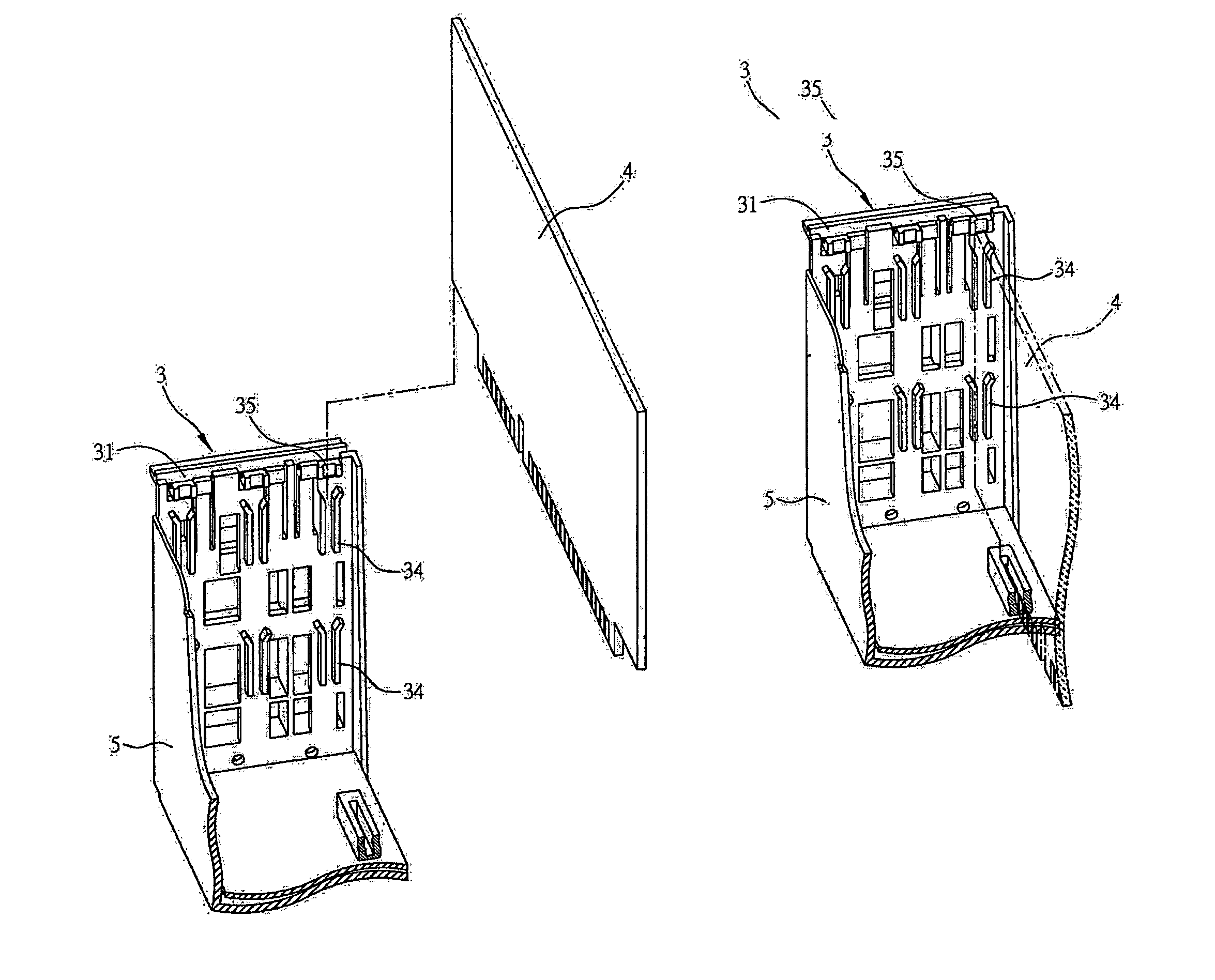
[0025]A fastening structure 3 of the present invention is applicable to an electronic device, such as a desktop PC, a notebook computer or a server, for fastening an add-on card in the housing of an electronic device....


PUM


Abstract

An add-on card fastening structure is proposed, which is used for fastening an add-on card on a housing of an electronic device, wherein the housing of the electronic device is provided with a first positioning portion and a first coupling portion. The add-on card fastening structure includes a body, a second positioning portion, a second coupling portion, a plurality of confining portions, and a stop portion. The second positioning portion is disposed on the body and positionally corresponds to the first positioning portion. The second coupling portion is disposed on the body and can be coupled to the first coupling portion. The plurality of confining portions are disposed on the body so as to confine the add-on card in the fastening structure. The stop portion is disposed on the body so as to stop any displacement of a top portion of the add-on card.

Description

BACKGROUND OF THE INVENTION[0001]1. Field of the Invention[0002]The present invention relates to a design of a fastening structure, and more particularly, to a fastening structure for fastening an add-on card in a housing of an electronic device.[0003]2. Description of the Prior Art[0004]With constant advancement and development of technology, electronic devices have become indispensable to modern people's daily lives. An electronic device (for example, a host computer or a server) is composed of plenty major components and parts, such as a disk drive, a power supply, and a motherboard, disposed inside the housing of the electronic device. The motherboard is equipped with various slots, for example, accelerated graphics port (AGP), peripheral component interconnect (PCI), and industrial standard architecture (ISA), into which a display card, a sound card, and a network interface card are inserted so as to enhance the functions of the electronic device.[0005]FIG. 1 shows a three-dime...

Claims


Application Information

Patent Timeline
IPC IPC(8): H05K7/12
CPCG06F1/186H05K7/1408
Inventor CHANG, LIN-WEI
Owner INVENTEC CORP
Why Eureka
Try Eureka