Clock generator having a delay locked loop and duty cycle correction circuit in a parallel configuration

a technology of delay lock and duty cycle correction, which is applied in the field of integrated circuits, can solve the problems of increasing the time delay introduced by the internal circuitry, the internal clock signal to be phase shifted relative to the external clock signal, and the command applied to the memory device may no longer be valid

Active Publication Date: 2007-06-05
MICRON TECH INC
View PDF100 Cites 87 Cited by
  • Summary
  • Abstract
  • Description
  • Claims
  • Application Information

AI Technical Summary

Problems solved by technology

Internal circuitry in the memory device that generates the internal clock signal necessarily introduces some time delay, causing the internal clock signal to be phase shifted relative to the external clock signal.
However, with higher frequency clock signals, the time delay introduced by the internal circuitry becomes more significant.
This is true because as the frequency of the external clock signal increases, the period of the signal decreases and thus even small delays introduced by the internal circuitry correspond to significant phase shifts between the internal and external clock signals.
As a result of inherent delays, the commands applied to the memory device may no longer be valid by the time the internal clock signal clocks the latches.
Additionally, as the frequency of the external clock increases, variations in the duty cycle of the clock signal introduce a greater duty cycle error.
In such instances, if the duty cycle of the clock signal is left uncorrected, timing errors may cause the memory device to fail.
This arrangement requires a clock signal to propagate through a plurality of adjustable delay lines, each of which have an adjustable delay that is potentially affected by such factors as the consumption of power or space, and by the operating limitations of the circuit.
Although the conventional clock generator 100 can successfully generate a synchronized clock signal having a 50% duty cycle, the conventional arrangement of the DLL 110 and the DCC circuit 120 is susceptible to several issues.
One issue is clock jitter.
As the delay times of the delay stages fluctuate, the resulting clock signal will drift or “jitter.” The fluctuations in delay time can be caused by power supply noise, which affects the delay time of each active delay stages of an adjustable delay line.
Propagating the clock signal through one more adjustable delay line will only result in generating a clock signal having yet more clock jitter.
Moreover, the cascaded structure of variable delays results in relatively high power consumption, in addition to the problems with jitter as previously described, that can be compounded by the power supply noise potentially occurring at each stage of the delay, making an undesirable situation even worse.
Other issues with the arrangement of the DLL 110 and the DCC circuit 120 of the clock generator 100 are slowness of operation and cumbersome size.
The clock generator 100 is cumbersome because the circuit includes nearly two complete DLLs.
A variable delay typically takes up a relatively large amount of space on a semiconductor substrate on which the clock generator and other components of a memory device are formed.
Having multiple variable delays of similar delay length only exacerbates the issue and can be undesirable where the general design goal is reducing circuit size.

Method used


Image

  • Clock generator having a delay locked loop and duty cycle correction circuit in a parallel configuration
  • Clock generator having a delay locked loop and duty cycle correction circuit in a parallel configuration
  • Clock generator having a delay locked loop and duty cycle correction circuit in a parallel configuration

Examples


Embodiment Construction

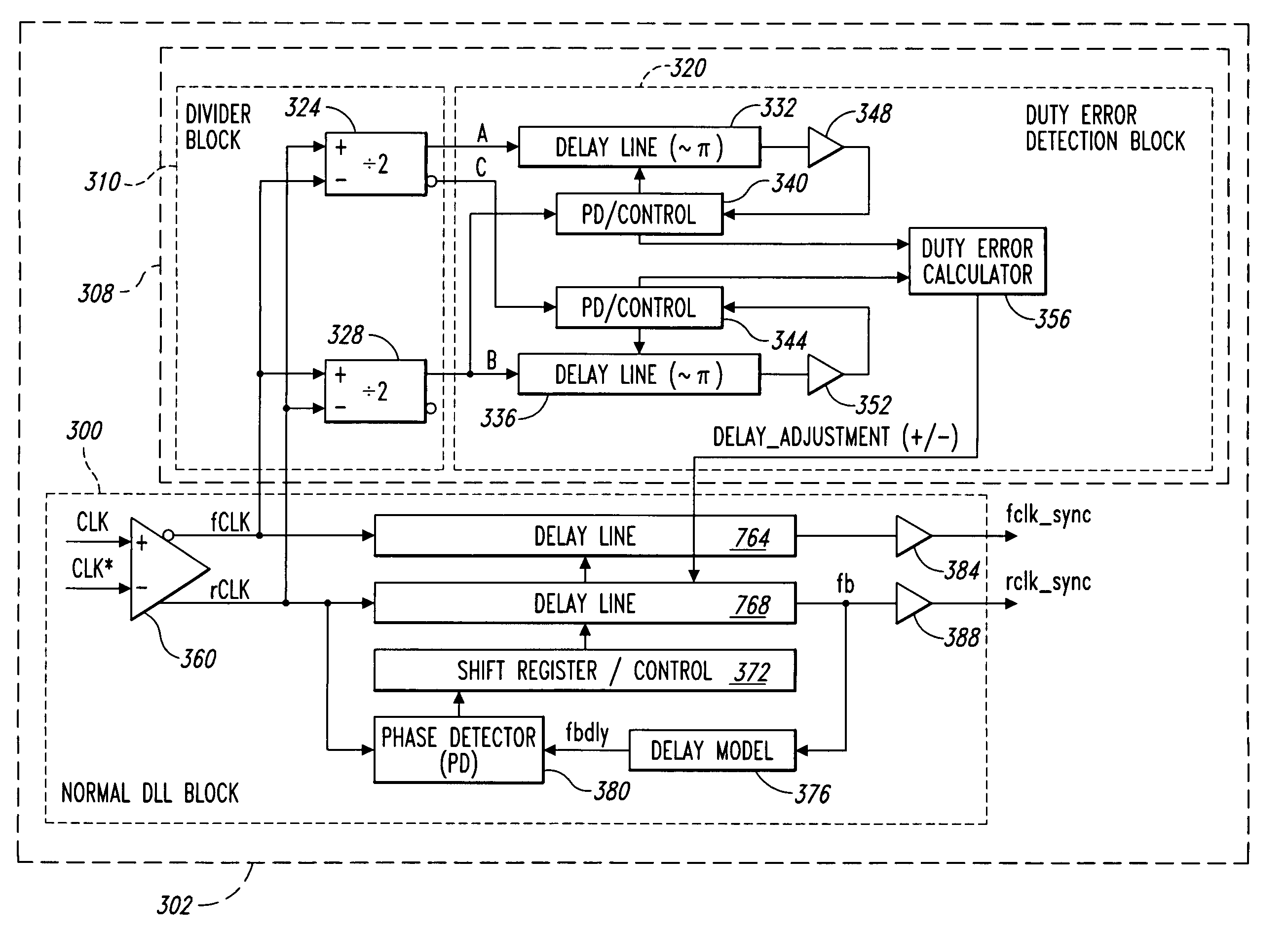
[0024]Embodiments of the present invention are directed to a clock generator that includes a DCC circuit that is connected in parallel to a DLL, and functions independently of the DLL. By separating the locking function and duty cycle correction, the time for generating stable, synchronized, duty cycle corrected clock signals is improved and power and area consumption are reduced. Additionally, clock jitter due to power supply noise is reduced due to using shorter delay lines for duty cycle correction. In the following description, certain details are set forth below to provide a sufficient understanding of the invention. However, it will be clear to one skilled in the art that the invention may be practiced without these particular details. In other instances, well-known circuits, control signals, timing protocols, and software operations have not been shown in detail or omitted entirely in order to avoid unnecessarily obscuring the invention.

[0025]In contrast to conventional embod...


PUM


Abstract

A clock generator having a delay locked loop and a duty cycle correction circuit. The delay locked loop adjusts a first adjustable delay circuit to generate a first output clock signal that is synchronized with a first input clock signal and adjusts a second adjustable delay circuit to provide a delay that is equal to the first adjustable delay circuit. A duty cycle correction circuit is coupled to the first and second inputs of the delay locked loop and further coupled to the second adjustable delay circuit. The duty cycle correction circuit is configured to determine a duty cycle error of at least one of the first and second input clock signals and adjust the second adjustable delay circuit to provide a corrected delay compensating for the duty cycle error.

Description

TECHNICAL FIELD[0001]The present invention relates generally to integrated circuits, and more specifically to synchronizing an external clock signal applied to an integrated circuit with internal clock signals generated in the integrated circuit in response to the external clock signal, and generating a synchronized external clock signal having a corrected duty cycle.BACKGROUND OF THE INVENTION[0002]In synchronous integrated circuits, the integrated circuit is clocked by an external clock signal and performs operations at predetermined times relative to the rising and falling edges of the applied clock signal. Examples of synchronous integrated circuits include synchronous memory devices such as synchronous dynamic random access memories (“SDRAMs”), synchronous static random access memories (“SSRAMs”), and packetized memories like SLDRAMs and RDRAMs, and include other types of integrated circuits as well, such as microprocessors. The timing of signals external to a synchronous memor...

Claims


Application Information

Patent Timeline
Patent Type & Authority Patents(United States)
IPC IPC(8): G11C8/00
CPCG11C7/02G11C7/22G11C7/222G11C8/12G11C11/4076H03K5/151H03K5/1565H03L7/0814G11C2207/2254H03L7/0816
Inventor KWAK, JONGTAE
Owner MICRON TECH INC
Why Eureka
Try Eureka