Planar light source device and display device using the same

a technology of light source device and display device, which is applied in the direction of lighting support device, lighting and heating apparatus, instruments, etc., can solve the problems of lowering display quality, generating luminance and chromaticity unevenness, and lowering display quality

Active Publication Date: 2007-06-12
TRIVALE TECH
View PDF13 Cites 73 Cited by
  • Summary
  • Abstract
  • Description
  • Claims
  • Application Information

AI Technical Summary

Problems solved by technology

Since cold-cathode tubes having low directivity as a light source are used in a conventional planar light source device, there has been a problem that the quality of display is lowered, since focusing property at a condenser lens is low, luminance nearby the light source comes to be higher in comparison with luminance at a position far from the light source, the unevenness of luminance and the unevenness of chromaticity are generated in display.
Further, when light emitting diodes having high directivity are used as a light source, there has been a problem that the quality of display is lowered, since the unevenness of luminance and the unevenness of chromaticity are generated in display in accordance with the light distribution of point light sources.

Method used


Image

  • Planar light source device and display device using the same
  • Planar light source device and display device using the same
  • Planar light source device and display device using the same

Examples


embodiment 1

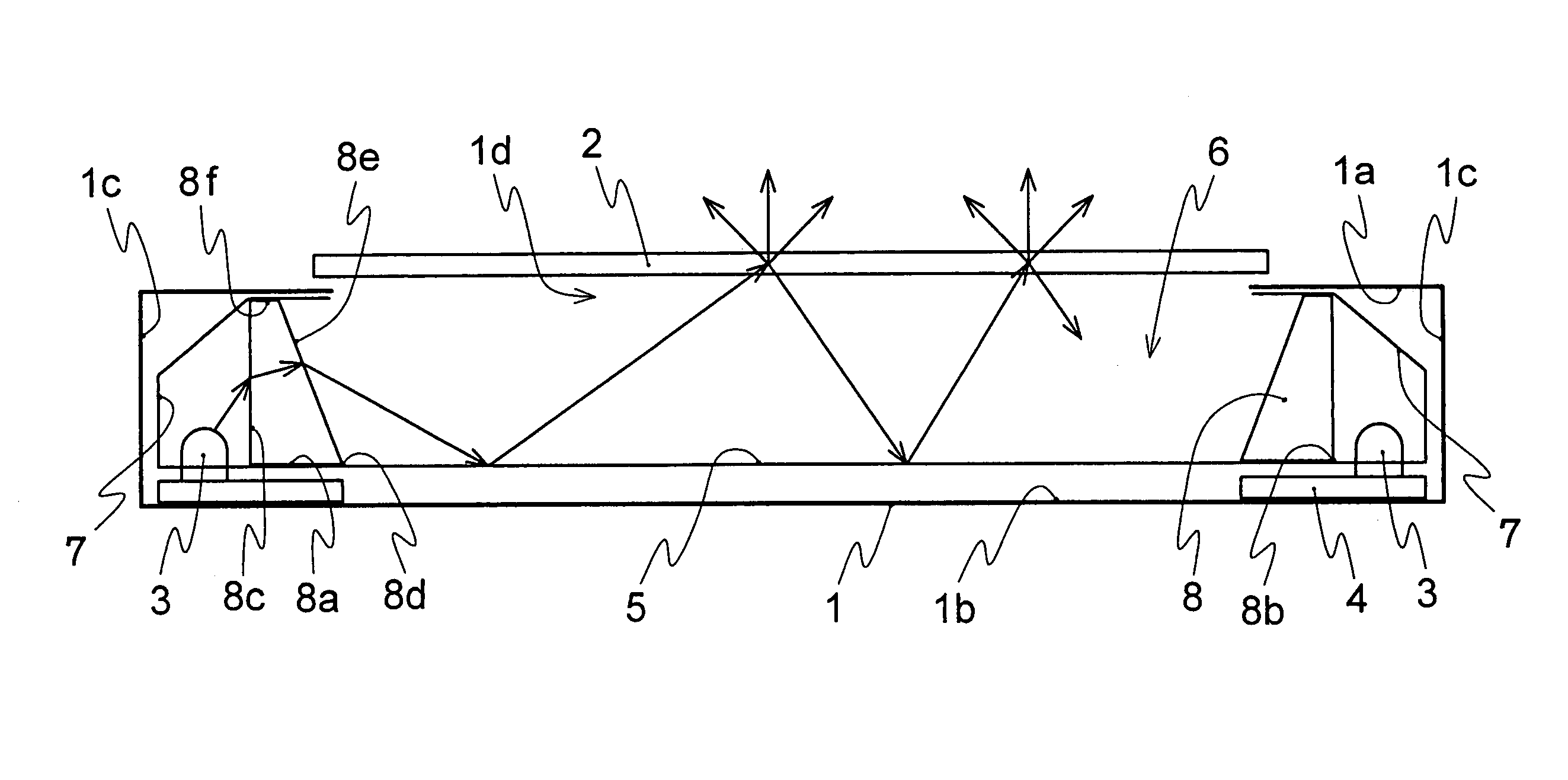
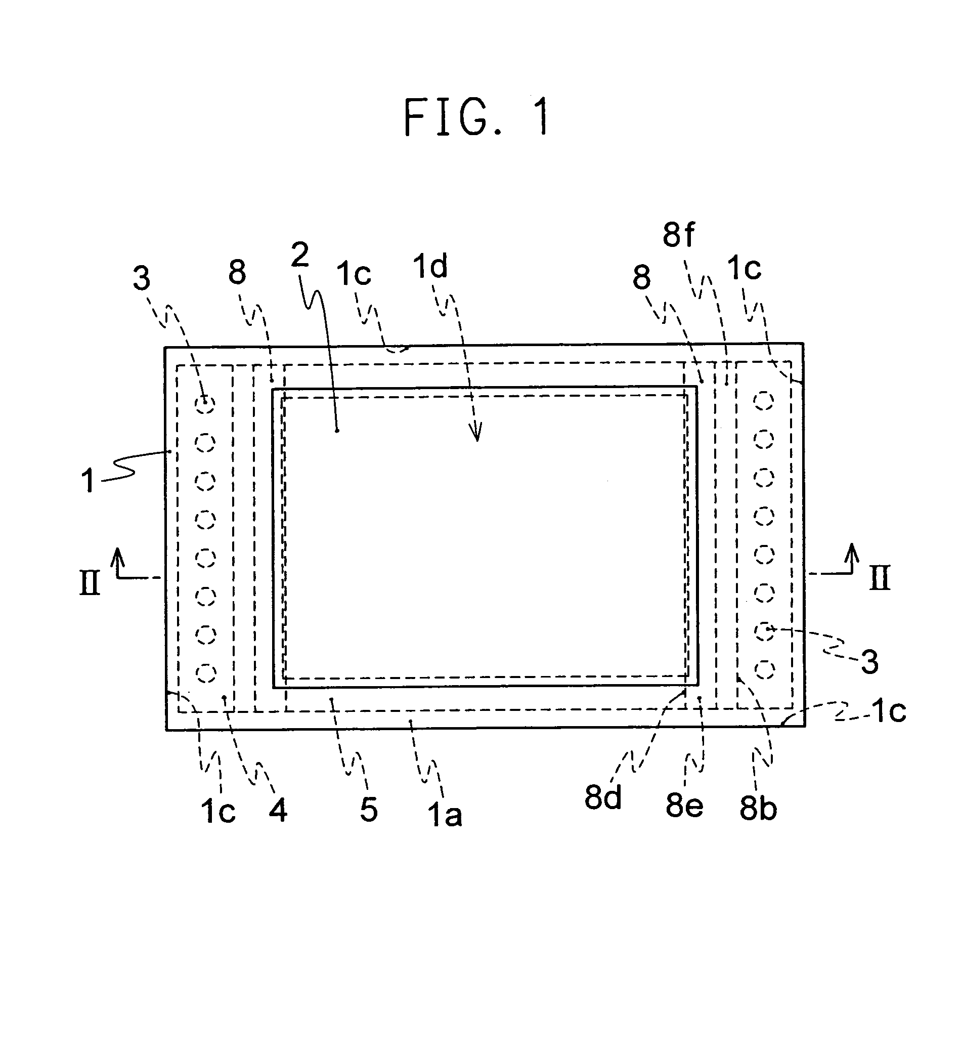
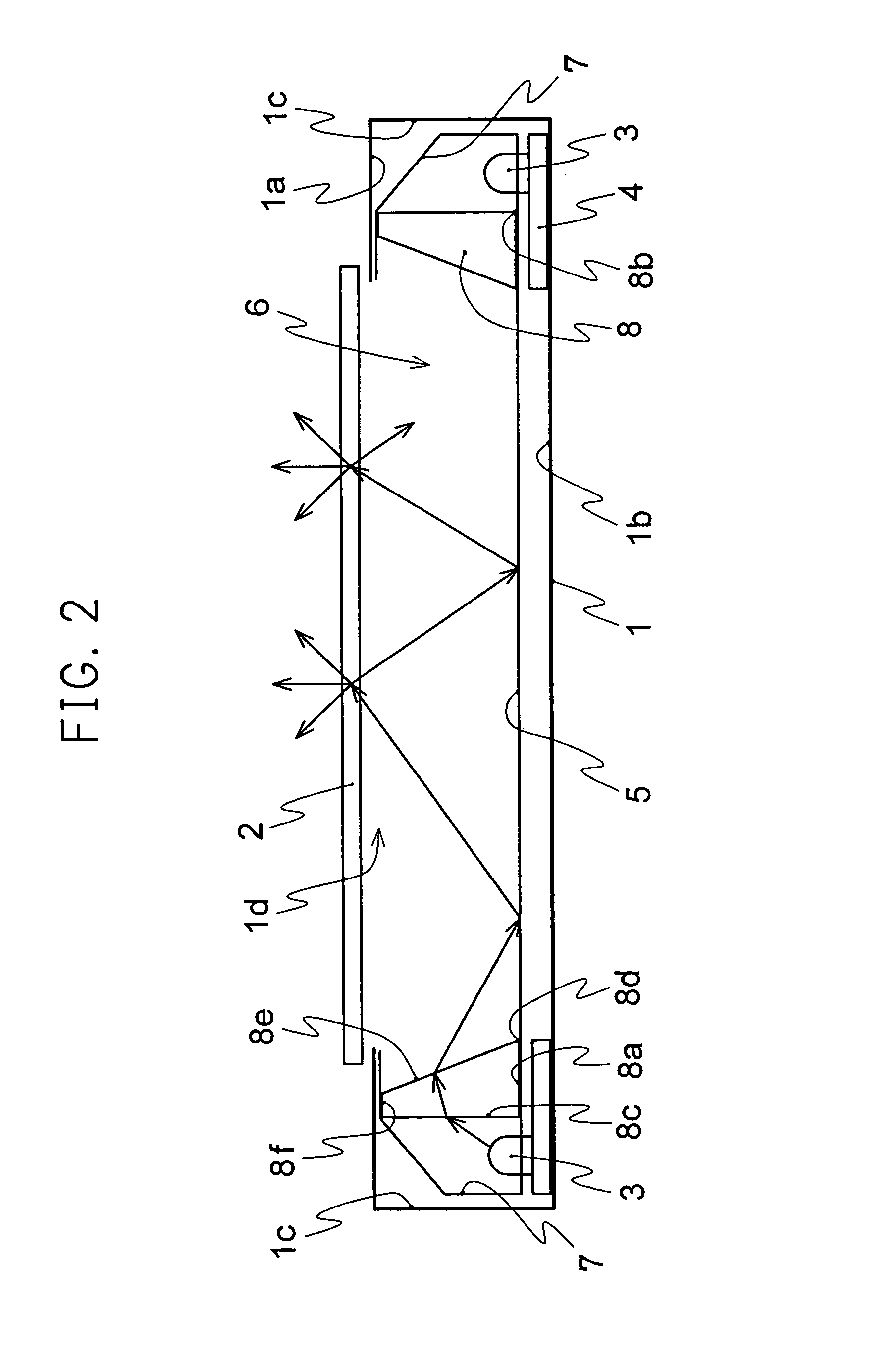
[0068]FIG. 1 is a plan view showing the schematic composition of a planar light source device related to Embodiment 1 of the present invention. FIG. 2 is a partial section view of the II—II line of the planar light source device shown in FIG. 1. FIG. 3 is an LED arrangement chart showing one example of the arrangement of point light sources 3 using light emitting diodes (LEDs) and the like. FIG. 4 is a magnified view of a substantial part for illustrating the light path of light passing the refractive element. FIG. 5 is a view showing the light distribution of radiating light from LEDs which are used for the point light sources 3 related to Embodiment 1 of the present invention. In FIGS. 1 to 5, the housing 1 of the planar light source device is composed of a top face 1a, a bottom face 1b and 4 side planes 1c and has an opening portion 1d on the top face 1a.

[0069]The whole opening portion 1d of the housing 1 is provided with a scattering plate 2. The scattering plate 2 is a glass s...

embodiment 2

[0147]FIG. 26 is a partial section view of the planar light source device related to Embodiment 2 of the present invention. FIGS. 27(a) to 27(c) are partial section views of other refractive element related to Embodiment 2. In FIG. 26, the same numerals as FIGS. 1 to 25 show the same portions or equivalent portions, and their illustration is abbreviated. The refractive element 11 has the bottom face 11a which is nearly parallel to the bottom face 1b of the housing 1 or the scattering plate 2, the irradiated plane 11c which forms a fixed oblique angle θ1 at the reverse side from the first crista 11b to the bottom face 1b side of the housing 1 against the parallel bottom face 11a which passes the first crista 11b of the bottom face 11a in the point light sources 3 side, a plurality of faces 11g which are nearly parallel to the bottom face 11a, the radiating planes 11e which form a fixed oblique angle θ2 at the reverse side from the cristas 11d to the bottom face 1b side of the housing...

embodiment 3

[0155]FIG. 28 is a partial section view of the planar light source device related to Embodiment 3 of the present invention. FIGS. 29(a) and 29(b) are evolution charts showing the refractive element related to Embodiment 3, FIG. 29(a) is a top view viewed from the top face side of the housing, and FIG. 29(b) is a frontal view viewed from the hollow space side. FIG. 30 is an illustration view showing a light path possibly occurring when light transmitting in the refractive element is totally reflected on a radiating plane. In FIGS. 28 to 30, the same numerals as FIGS. 1 to 27(c) show the same portions or equivalent portions, and their illustration is abbreviated.

[0156]The refractive element 12 has the bottom face 12a which is nearly parallel to the bottom face 1b of the housing 1 or the scattering plate 2, the irradiated plane 12c which forms a fixed oblique angle θ1 at the reverse side from the first crista 12b to the bottom face 1b side of the housing 1 against the bottom face 12a w...


PUM


Abstract

To obtain a planar light source which is free from brightness variations or chromaticity variations by using a point light source having a high directivity for emitted light, and to provide a liquid crystal display device capable of obtaining superior display characteristics by using this planar light source device. A planar light source device having an opening in the upper surface comprises a hollow box, a diffusion plate disposed in the opening, a reflecting plate disposed on the bottom of the hollow region of the box, and a plurality of point light sources disposed in a row along at least one side surface of the box. This planar light sources device is characterized by including a refracting element disposed parallel to the row of point light sources and between the point light sources and the hollow region for refracting the light from the point light sources, whereby the light at an incident angle at which the brightness is greatest in the luminous intensity distribution of the light radiated to the irradiation subject surface of the refracting element is refracted to the bottom surface of the box by the refracting element.

Description

TECHNICAL FIELD[0001]The present invention relates to a hollow type planar light source device which does not employ light guiding plate. More specifically, the present invention relates to a planar light source device using a plurality of point light sources such as light emitting diodes which emit monochromatic lights such as R (red), G (green) and B (blue), and a display device using the device.BACKGROUND ART[0002]In a conventional planar light source device, the portion of light radiated from a cold-cathode tube and light which is radiated from the cold-cathode tube and reflected on the cylindrical surface of a light source cover becomes parallel light with a focus lens and radiated on the reflection plane of a reflecting plate, and the reflected light is scattered from a scattering plate to be radiated (for example, refer to Japanese Unexamined Patent Publication No. 54625 / 1996 (page 3, line 18 of the left column to line 45 of the right column, FIG. 2)).[0003]Further, other con...

Claims


Application Information

Patent Timeline
Patent Type & Authority Patents(United States)
IPC IPC(8): F21V33/00F21V8/00
CPCG02B6/0051G02B6/0096G02B6/0023G02B6/0031G02F1/133615F21Y2105/10
Inventor SAKAI, SEIJIMORI, AKIHIROYAMAGUCHI, TAKASHIYONEDA, TOSHIYUKI
Owner TRIVALE TECH
Why Eureka
Try Eureka