Portable mixing apparatus

a mixer and portable technology, applied in the field of portable mixers, can solve the problems of insufficiently satisfying the above criteria of mixers, inconvenient and efficient use, and insufficient portability of existing motor-driven mixers, and achieve the effect of convenient transportation

Inactive Publication Date: 2007-06-12
HASKELL GEORGE L
View PDF32 Cites 18 Cited by
  • Summary
  • Abstract
  • Description
  • Claims
  • Application Information

AI Technical Summary

Benefits of technology

[0010]The present invention has solved the problems cited above, and is a compact, easily transportable mixing apparatus that employs disposable 5-gallon plastic buckets as the containers for mixing mortar, grout, plaster and other materials.

Problems solved by technology

Currently available mixers do not adequately satisfy the foregoing criteria.
Mortar or grout can, of course, be mixed the “old fashioned” way simply using a bucket and trowel, however this is neither convenient nor efficient, except for very small amounts of material.
On the other hand, existing motor-driven mixers are expensive and lack adequate portability.
Not only are the mixers themselves bulky and difficult to transport they are also cumbersome to use, since the drum must be dumped out into a smaller, second container (such as a bucket or tray) from which the mortar / grout is then applied.
In practice, however, this class of devices is highly unsatisfactory for several reasons, including inadequate mixing of the materials and the messy, cumbersome and physically tiring action that is inherent in their operation; moreover, the fact that they are manually operated means that other work must be stopped while the mortar / grout is being mixed.
Another existing device resembles a small “roto-tiller” that mixes the material in a plastic trough, which combines the drawbacks of the “electric drill” type mixers with the cost, portability and cleaning problems associated with drum mixers.

Method used


Image

  • Portable mixing apparatus
  • Portable mixing apparatus
  • Portable mixing apparatus

Examples


Embodiment Construction

a. Overview

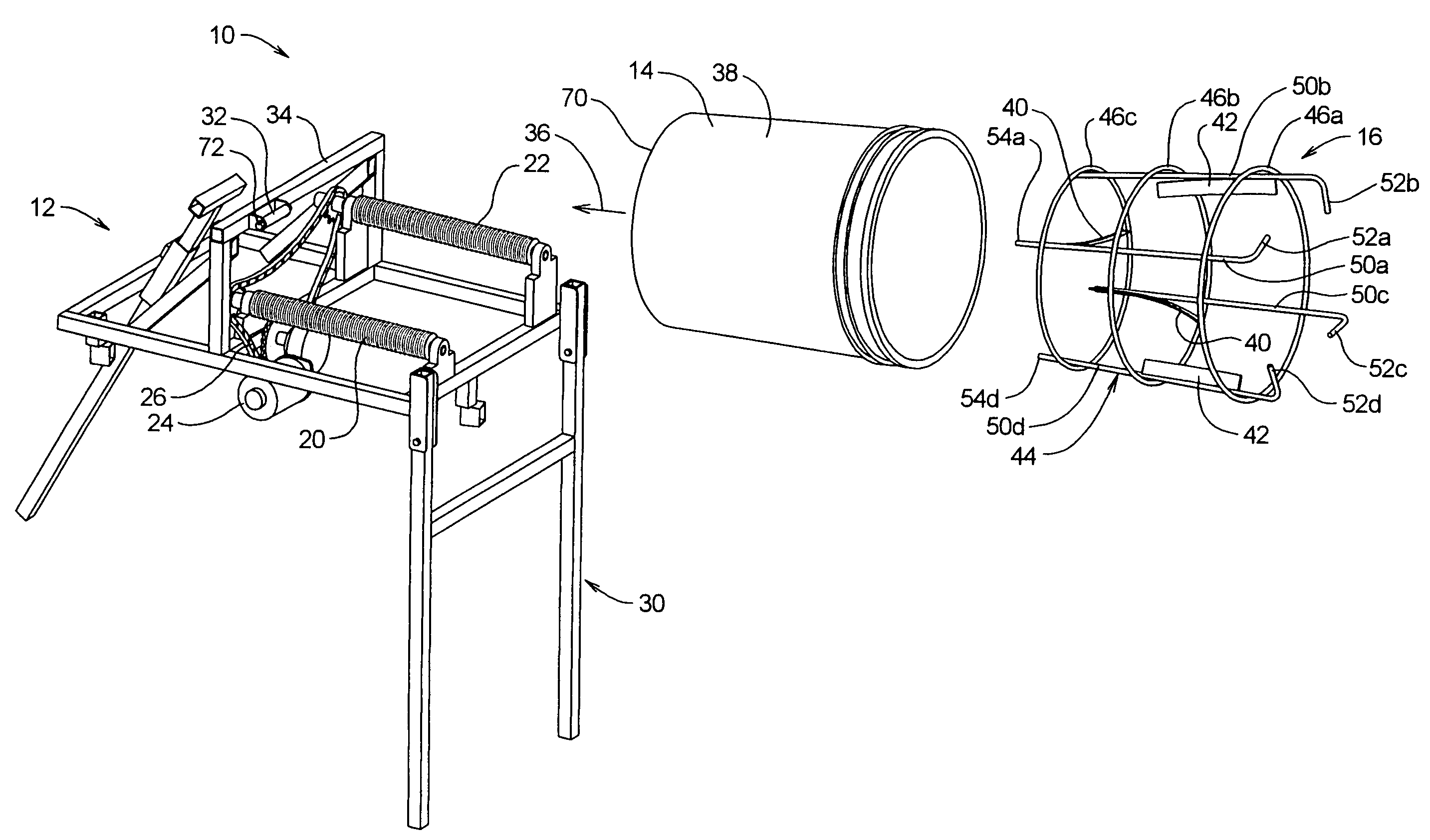
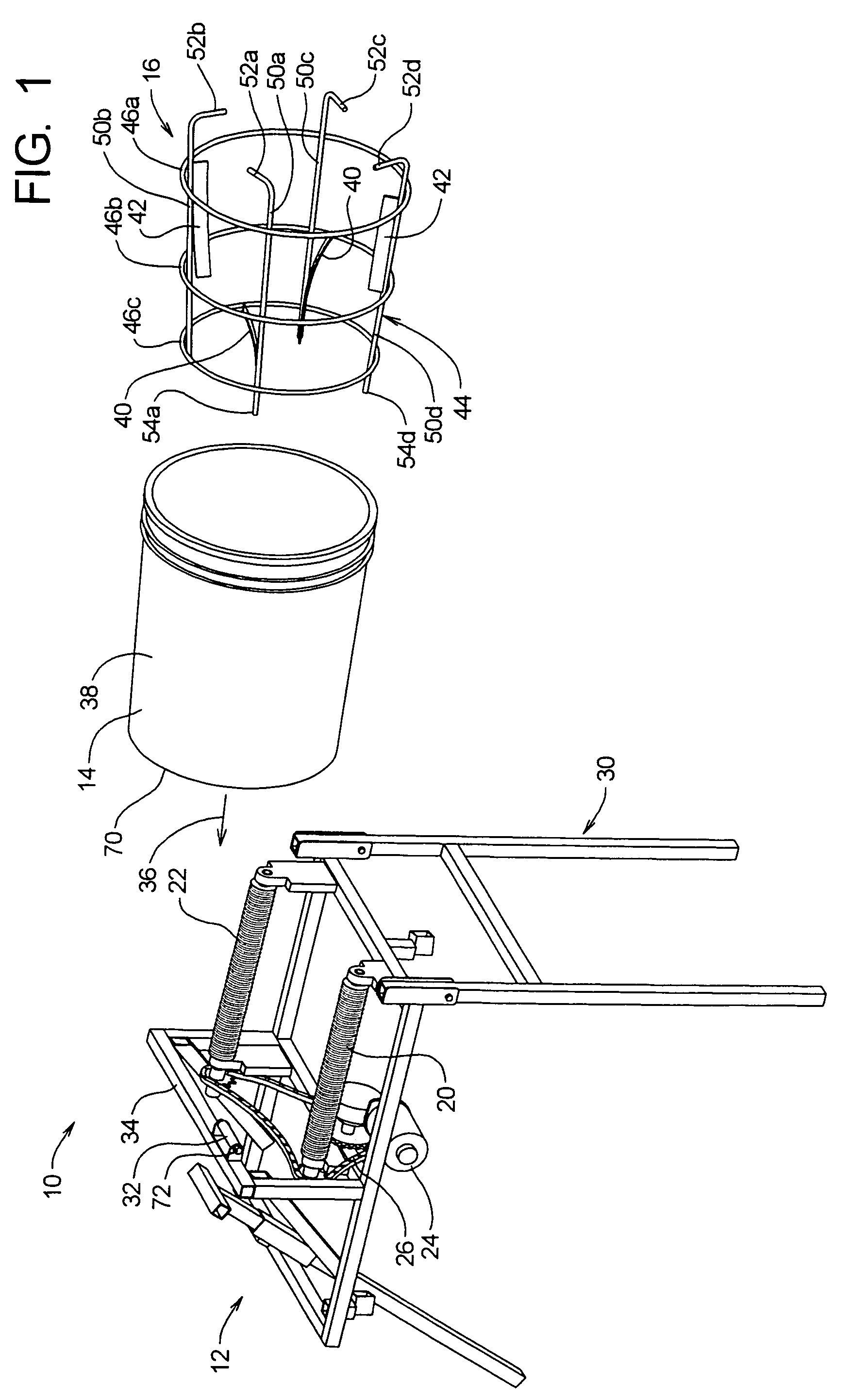
[0028]As noted above, the present invention provides an apparatus by which mortar, grout, plaster and similar materials are be mixed on the jobsite in one or more ordinary 5-gallon plastic buckets. The apparatus is inexpensive, efficient and highly portable.

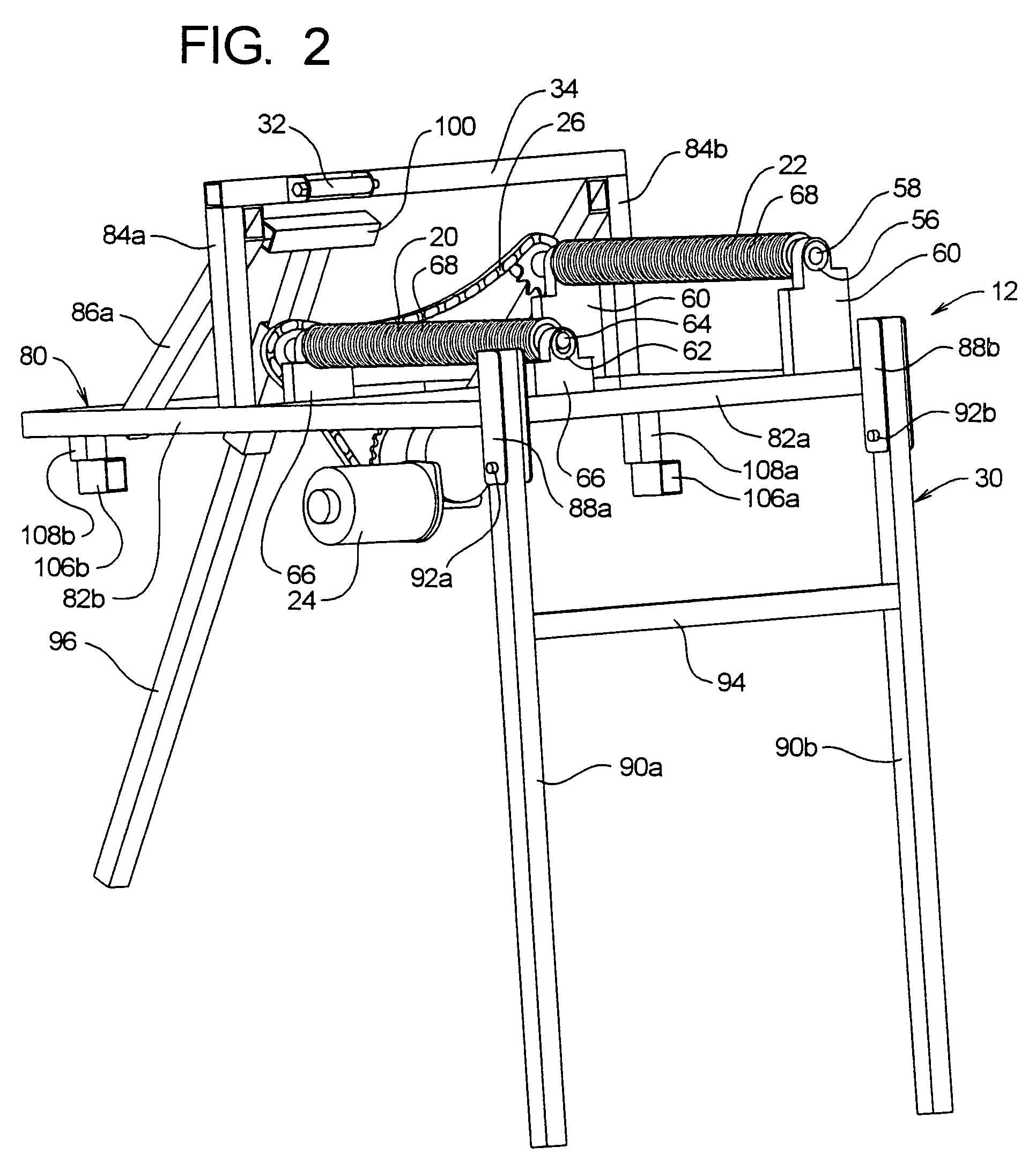
[0029]As can be seen in FIG. 1, the apparatus 10 of the present invention includes two primary subassemblies, i.e., a drive assembly 12 that rotates the plastic bucket 14, and a multi-bladed mixer basket 16 that is placed within the interior of the bucket.

[0030]The bucket 14 is an ordinary 5-gallon plastic bucket, such as are used in large quantities as containers for many different types of products, in the food and construction industries and elsewhere; for example, 5-gallon buckets are commonly employed as containers for paint. The popularity of 5-gallon buckets is due in large part to the fact that this is a particularly convenient size for handling most fluid or semi-fluid materials, which makes them likewise adva...


PUM

PropertyMeasurementUnit
areaaaaaaaaaaa
power transmissionaaaaaaaaaa
angleaaaaaaaaaa

Abstract

A portable mixing apparatus that employs disposable 5-gallon plastic buckets as containers for mixing mortar, grout, plaster and other materials. First and second motor-driven rollers support the buckets at a downwardly sloped angle. A separate mixing basket is placed within the buckets, and includes a plurality of blades that pass through the material as the bucket is rotated by the rollers. The leading roller is positioned lower than the trailing roller so as to engage the flexible wall of the bucket in an area where it is subject to outward pressure from the material during rotation. The rollers are provided with ribbed, non-slip covers having channels that accommodate water and debris on the exteriors of the buckets. The mixing basket is formed of a plurality of coaxial, longitudinally-spaced rings joined at their edges by longitudinal rods. The blades are mounted internal to the rings and extend generally parallel to the axis of the buckets, with the ends of the rods being angled in the direction of rotation. The drive rollers and motor are mounted in a frame having folding legs so that the assembly can be collapsed to a compact form for transportation or storage.

Description

BACKGROUND OF THE INVENTION[0001]a. Field of the Invention[0002]The present invention relates generally to an apparatus for mixing mortar, cement, and similar materials, and, more particularly, to a portable mixer for preparing such materials in ordinary disposable plastic buckets.[0003]b. Related Art[0004]Certain materials and compositions require mixing prior to use, particular examples of such materials being grout, mortar, plaster and cement. For example, masonry work or tile work typically requires that the mortar or grout be mixed at the jobsite immediately before use.[0005]Unlike concrete, which is typically obtained in large volumes from a ready-mix plant or a mixer truck, mortar and grout work employ fairly small batches of material. For example, a brick mason or tile setter will typically prepare a small batch or mortar or grout for work at a first job site and then move to another job site and prepare another batch of material, as, for example, when moving from one house ...

Claims


Application Information

Patent Timeline
Patent Type & Authority Patents(United States)
IPC IPC(8): B01F9/08B01F29/63B01F29/64
CPCB01F9/0016B01F9/06B28C5/0843B28C5/1806B01F13/0018B01F2009/0063B01F2215/0047B01F29/31B01F29/4033B01F29/63B01F33/501B01F2101/28
Inventor HASKELL, GEORGE L.
Owner HASKELL GEORGE L
Why Eureka
Try Eureka