Rotor hub fairing system for a counter-rotating, coaxial rotor system

a rotor hub and coaxial technology, applied in the direction of rotors, marine propulsion, vessel construction, etc., can solve the problems of significant power penalty and significant drag increase of the rotor system of rotary wing aircraft, and achieve the effect of reducing the overall drag of the rotor system, and reducing the overall drag

Active Publication Date: 2007-06-12
SIKORSKY AIRCRAFT CORP
View PDF9 Cites 51 Cited by
  • Summary
  • Abstract
  • Description
  • Claims
  • Application Information

AI Technical Summary

Benefits of technology

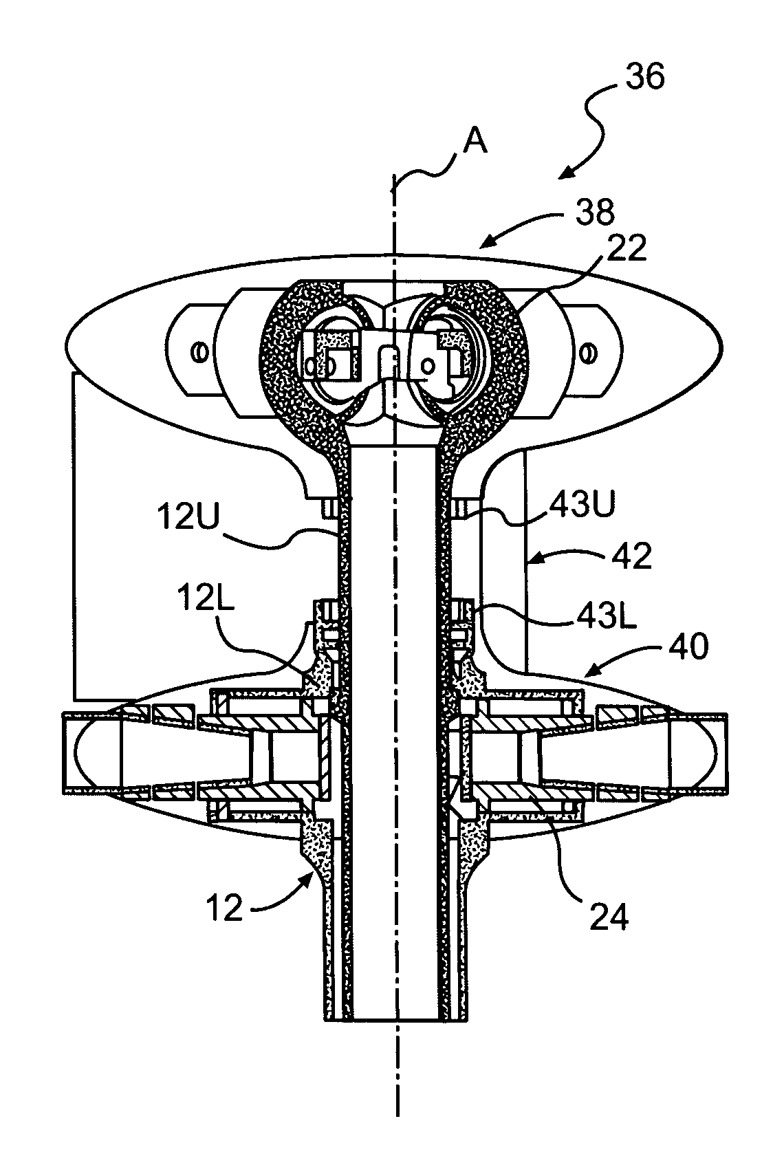
[0005]A rotor hub fairing system for a dual, counter-rotating, coaxial rotor system according to the present invention generally includes an upper hub fairing, a lower hub fairing and a shaft fairing located therebetween. The rotor hub fairing system is sized and configured to reduce the overall drag on the rotor system. Preferably, the rotor hub fairing system is an integrated system that is refined through analysis and / or testing to reduce overall drag. The rotor hub fairing is viewed as a system for drag reduction, rather than drag reduction by the individual components. The rotor hub fairing system reduces drag by minimizing excessive separation in the surface junction areas. Furthermore, by introducing an integrated design, drag is reduced by accounting for the interference effects and optimal surface distributions for each rotor system configuration. The use of fillets at the intersecting surfaces further reduces the overall drag.
[0006]The shaft fairing preferably includes a minimal thickness at the shaft fairing's midsection. The outer shaft fairing sections on each side of the shaft fairing midsection and adjacent the upper and lower hub fairings define a thickness greater than the shaft fairing's midsection. Minimizing the thickness at the midsection reduces drag while increasing the thickness at the outer shaft fairing sections reduces the flow separation on the hub fairing surfaces.
[0007]According to another embodiment of the present invention, the rotor hub fairing system may include a horizontal wing-like splitter airfoil which extends from the shaft fairing, preferably at the midsection. The splitter airfoil includes an airfoil profile which reduces drag and sensitivity to angle of attack variations. The airfoil shape of the splitter airfoil may provide a fixed or adjustable angle of attack to specifically tailor the rotor hub wake in a direction that reduces airframe and tail vibration.
[0008]According to yet another embodiment of the present invention, the rotor hub fairing system may include a plurality of turning vanes which facilitate flow around the aft end of the upper and lower hub fairings to reduce flow separation and drag. The rotor hub fairing system may include a plurality of turning vanes located adjacent the lower hub, a plurality of turning vanes located adjacent the upper hub or any combination thereof. The upper turning vane may be located adjacent the upper hub fairing and includes a camber which preferably follows the contour of the upper hub fairing while the lower turning vane may be located adjacent the lower hub fairing and preferably includes a camber which follows the contour of the lower hub fairing.

Problems solved by technology

The rotor system drag increases significantly for a rotary wing aircraft having a counter-rotating, coaxial rotor system primarily due to the extra rotor hub and the interconnecting shaft between the upper and lower rotor systems.
For high-speed rotary wing aircraft, the increased drag resulting from the counter-rotating, coaxial rotor system may result in a relatively significant power penalty.

Method used


Image

  • Rotor hub fairing system for a counter-rotating, coaxial rotor system
  • Rotor hub fairing system for a counter-rotating, coaxial rotor system
  • Rotor hub fairing system for a counter-rotating, coaxial rotor system

Examples


Embodiment Construction

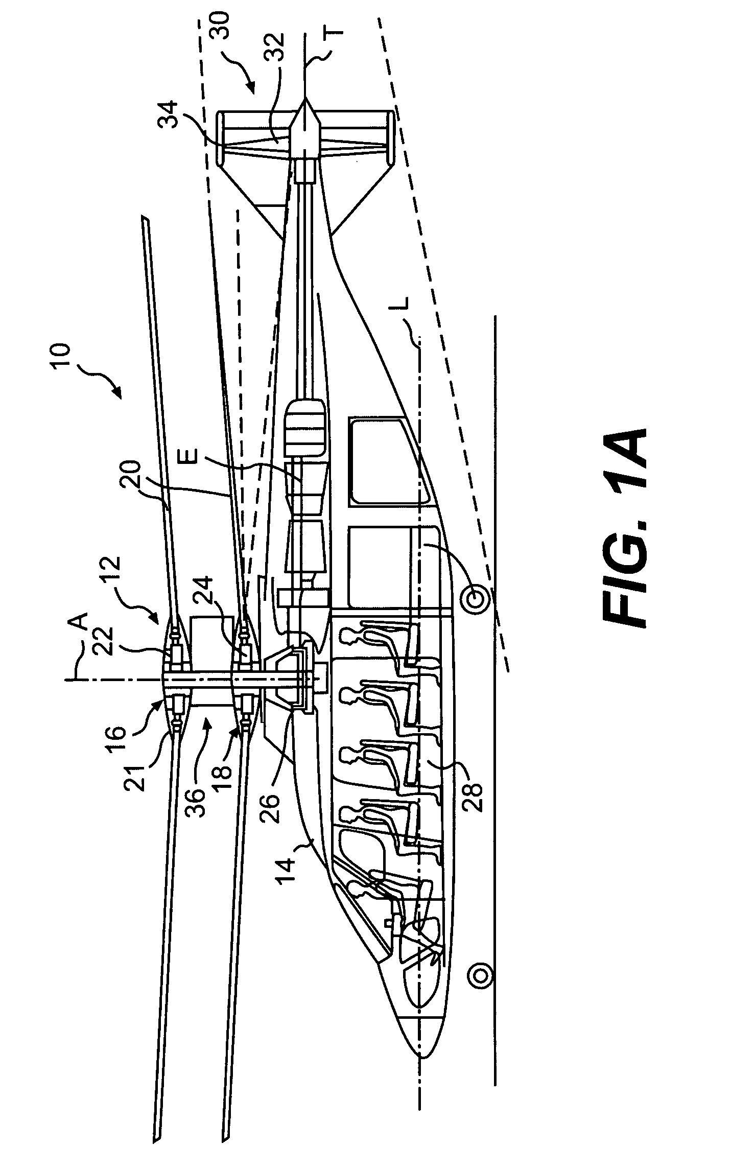
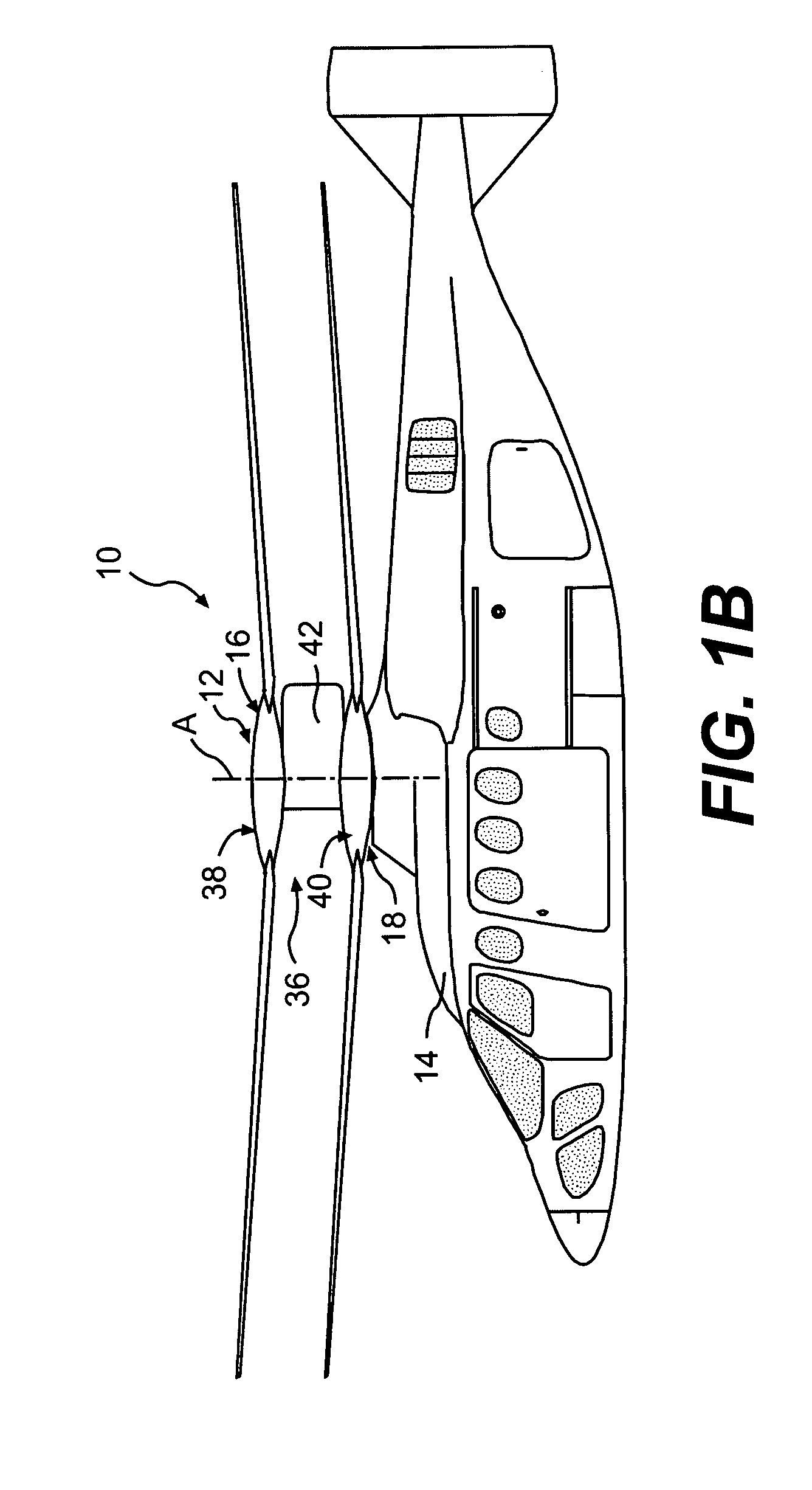
[0029]FIGS. 1A and 1B illustrate an exemplary vertical takeoff and landing (VTOL) high speed rotary-wing aircraft 10 having a dual, counter-rotating, coaxial rotor system 12. The aircraft 10 includes an airframe 14 which supports the dual, counter rotating, coaxial rotor system 12 as well as a translational thrust system 30 which provides translational thrust generally parallel to an aircraft longitudinal axis L. Although a particular aircraft configuration is illustrated in the disclosed embodiment, other machines will also benefit from the present invention.

[0030]The dual, counter-rotating, coaxial rotor system 12 includes an upper rotor system 16 and a lower rotor system 18. Each rotor system 16, 18 includes a plurality of rotor blades 20 mounted to a rotor hub 22, 24 for rotation about a rotor axis of rotation A. A plurality of the main rotor blades 20 project substantially radially outward from the hub assemblies 22, 24 and are connected thereto in any manner known to one of or...


PUM


Abstract

A rotor hub fairing system includes an upper hub fairing, a lower hub fairing and a shaft fairing therebetween. The rotor hub fairing system is sized and configured to reduce the overall drag on a dual, counter-rotating, coaxial rotor system. Preferably, the rotor hub fairing is fully integrated. The shaft fairing preferably includes a minimal thickness at the midsection to reduce drag with an increasing thickness adjacent the upper and lower hub fairings to reduce the flow separation on the hub fairing surfaces without overly excessive drag. Other aerodynamic structures, such as a horizontal splitter and / or a plurality of turning vanes may be mounted to the shaft fairing to facilitate flow around the upper and lower hub fairings to reduce flow separation and drag.

Description

BACKGROUND OF THE INVENTION[0001]The present invention is directed to a rotor hub fairing system, and more particularly, to an integrated rotor hub fairing which is sized and configured to reduce overall drag for a high-speed rotary-wing aircraft a counter-rotating, coaxial rotor system.[0002]Typically, the aerodynamic drag associated with a rotor hub on a rotary wing aircraft is a significant portion of the overall aircraft drag, typically 25% to 30% for conventional single-rotor helicopters. The rotor system drag increases significantly for a rotary wing aircraft having a counter-rotating, coaxial rotor system primarily due to the extra rotor hub and the interconnecting shaft between the upper and lower rotor systems. For high-speed rotary wing aircraft, the increased drag resulting from the counter-rotating, coaxial rotor system may result in a relatively significant power penalty.[0003]The aerodynamic drag of the dual counter-rotating, coaxial rotor system is generated by three ...

Claims


Application Information

Patent Timeline
Patent Type & Authority Patents(United States)
IPC IPC(8): B64C27/50
CPCB64C1/00B64C7/00B64C27/10B64C27/12B64C27/14B64C27/04B64C27/20
Inventor BERTOLOTTI, FABIO P.SCOTT, MARK W.WAKE, BRIAN E.EGOLF, T. ALANMCCORMICK, DUANE C.
Owner SIKORSKY AIRCRAFT CORP
Why Eureka
Try Eureka