Environmentally sealed connector with blind mating capability

a technology of environment sealing and blind mating, applied in the direction of securing/insulating coupling contact members, coupling device connections, coupling contact members, etc., can solve the problems of compounding the problem of blind mating capability, specific to each type of connector, and mating problems specific to each connector typ

Active Publication Date: 2007-06-12
BWI CO LTD SA +1
View PDF26 Cites 136 Cited by
  • Summary
  • Abstract
  • Description
  • Claims
  • Application Information

AI Technical Summary

Problems solved by technology

Problems encountered with connectors under conditions of blind mating primarily involve centering and alignment of the connectors for proper mating of the electrical contacts without damage to the contacts.
Additional mating problems, specific to each type of connector, may also arise.
Problems caused by the need for blind mating capability may be compounded when the connector must be designed to operate in adverse environmental conditions, for example, in high-pressure environments and / or in environments with a risk of exposure to excess moisture or contaminants.

Method used


Image

  • Environmentally sealed connector with blind mating capability
  • Environmentally sealed connector with blind mating capability
  • Environmentally sealed connector with blind mating capability

Examples


Embodiment Construction

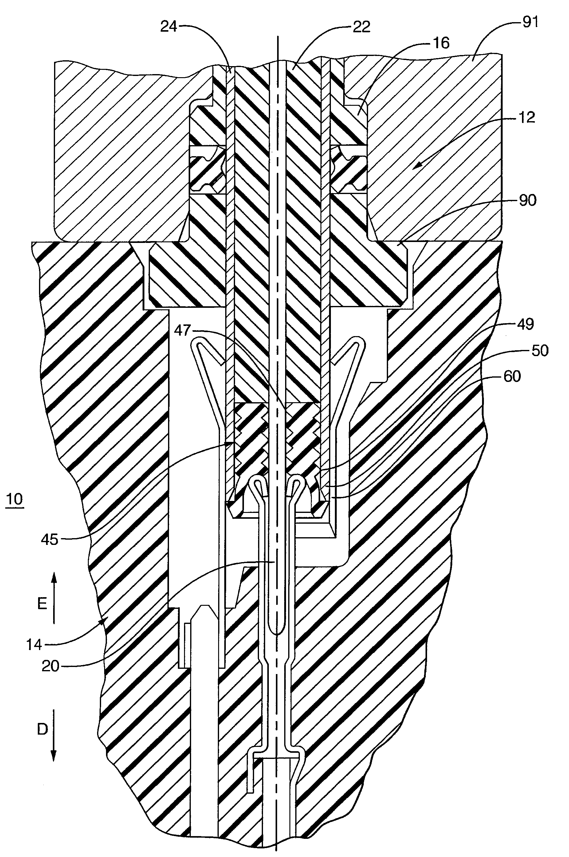
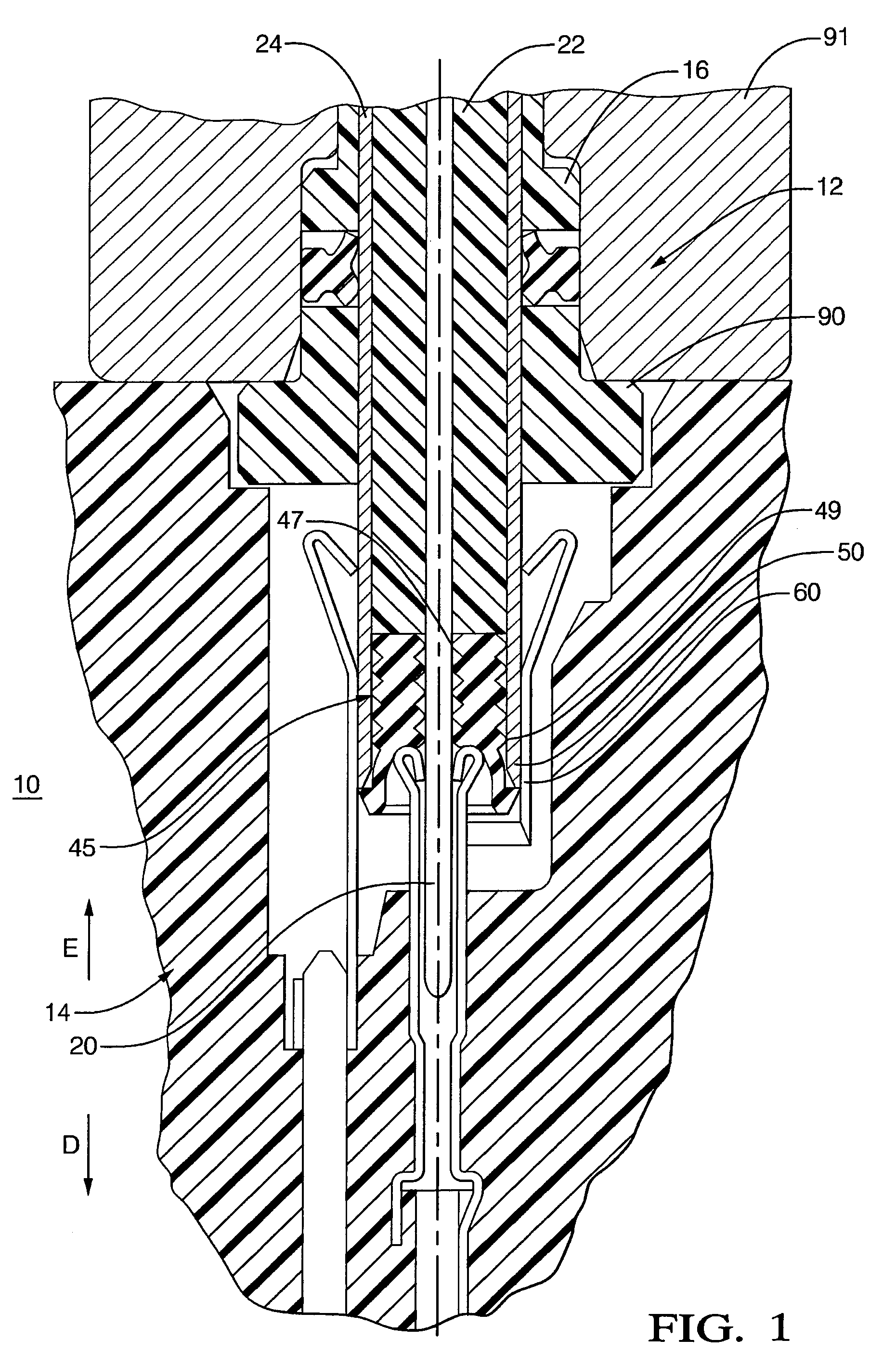
[0018]FIG. 1 shows a connector assembly 10 constructed in accordance with the present invention. Connector assembly 10 includes a first connector 12 and a second connector 14 configured to mateably engage first connector 12.

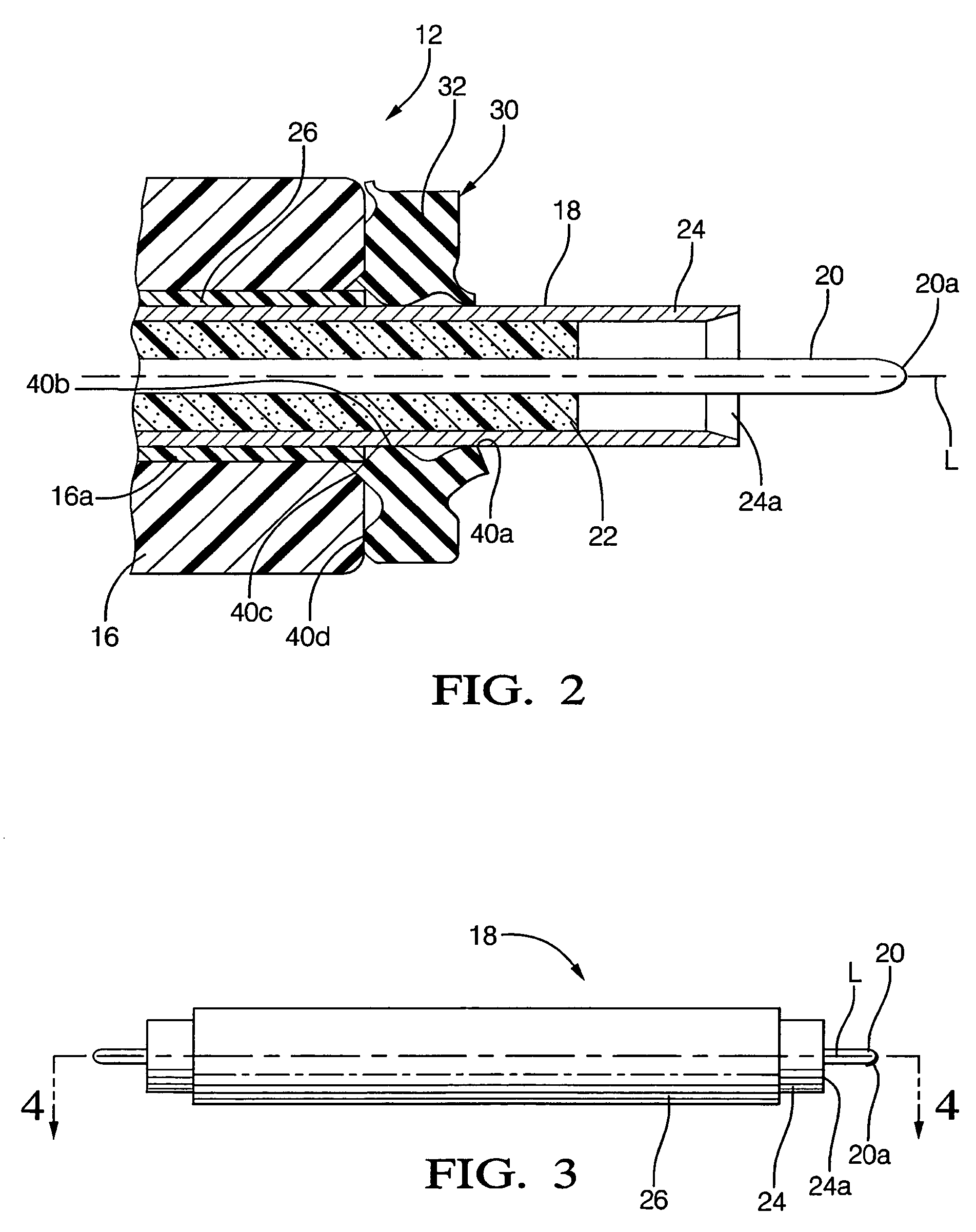
[0019]Referring to FIG. 2, first connector 12 includes a housing 16, a conductor assembly 18 positioned within housing 16 and projecting from housing 16, and a seal member 30 enclosing the interface between housing 16 and the portion of conductor assembly 18 projecting from the housing. Conductor assembly 18 projects through an orifice 16a formed in housing 16. Housing 16 is shaped to provide surfaces for manipulation by a user or by an automated assembly device, for purposes of mating the first connector 12 with second connector 14. Housing 16 is also shaped to provide surfaces that aid in locating and centering first connector 12 with respect to second connector 14 during mating of the connector assembly. In addition, housing 16 also aids in protecting conducto...


PUM


Abstract

A connector assembly (10) is provided including a first connector (12) and a second connector (14) configured to mateably engage the first connector (12). The first connector (12) includes a housing (16), a conductor assembly (18) positioned within the housing and projecting from housing, and a resilient seal member (30) enclosing an interface between the housing (16) and the portion of the conductor assembly projecting from the housing. The second connector (14) includes an outer contact (60), an inner contact (62) nested within a portion of the outer contact (60), and a housing (64) containing the inner and outer contacts. Conductors of the conductor assembly (18) of the first connector (12) engage the outer (60) and inner (62) contacts of the second connector (14). Another resilient seal member (45) includes a flexible skirt (50) formed at an end portion thereof. The flexible skirt (50) forms a shroud covering a mating interface between a first conductor (20) of the first connector (12) and the inner contact (62) of the second connector (14) when the first and second connectors are mated. Design features incorporated into the second connector housing (64), inner contact (62), and outer contact (60) act to retard undesirable unmating of the connectors. The connector assembly (10) of the present invention may be used in applications requiring a dual wire or coaxial connector resistant to adverse environmental conditions, such as exposure to high-pressure gases or liquids, elevated temperatures, vibration, salt spray, etc.

Description

CROSS REFERENCE TO RELATED APPLICATIONS[0001]This application claims the benefit of provisional application Ser. No. 60 / 648,224, filed on Jan. 28, 2005.BACKGROUND OF THE INVENTION[0002]The present invention relates to electrical connectors and, more particularly, to electrical connectors designed for blind mating and for use in adverse environmental conditions.[0003]In some connector applications, blind mating of connectors (i.e., mating with no visual feedback provided to a user during mating) is necessary. Problems encountered with connectors under conditions of blind mating primarily involve centering and alignment of the connectors for proper mating of the electrical contacts without damage to the contacts. Additional mating problems, specific to each type of connector, may also arise. For example, in the blind mating of coaxial connectors, the center conductor of the coaxial cable should possess sufficient rigidity to resist the insertion forces encountered during mating withou...

Claims


Application Information

Patent Timeline
Patent Type & Authority Patents(United States)
IPC IPC(8): H01R13/52
CPCH01R13/20H01R13/52H01R13/5205H01R13/521H01R13/5219H01R24/40H01R24/52H01R24/542H01R2103/00
Inventor VERMOESEN, MICHEL J.KRUCKEMEYER, WILLIAM C.NEAL, ROBERT A.MURPHY, KATHLEEN
Owner BWI CO LTD SA
Why Eureka
Try Eureka