
Apparatus and method for transient and uninterruptible power

Active Publication Date: 2007-06-12
ROCKWELL AUTOMATION TECH
View PDF8 Cites 44 Cited by
  • Summary
  • Abstract
  • Description
  • Claims
  • Application Information

AI Technical Summary

Benefits of technology

The system effectively bridges the power gap during outages, providing continuous power to critical devices without the high costs and space requirements of traditional systems, reducing the likelihood of system failure and data loss.

Problems solved by technology

However, if the external power supply to the apparatus is lost, then the exemplary apparatus functions as a transient power supply to coupled loads.

Method used


Image

  • Apparatus and method for transient and uninterruptible power
  • Apparatus and method for transient and uninterruptible power
  • Apparatus and method for transient and uninterruptible power

Examples


Embodiment Construction

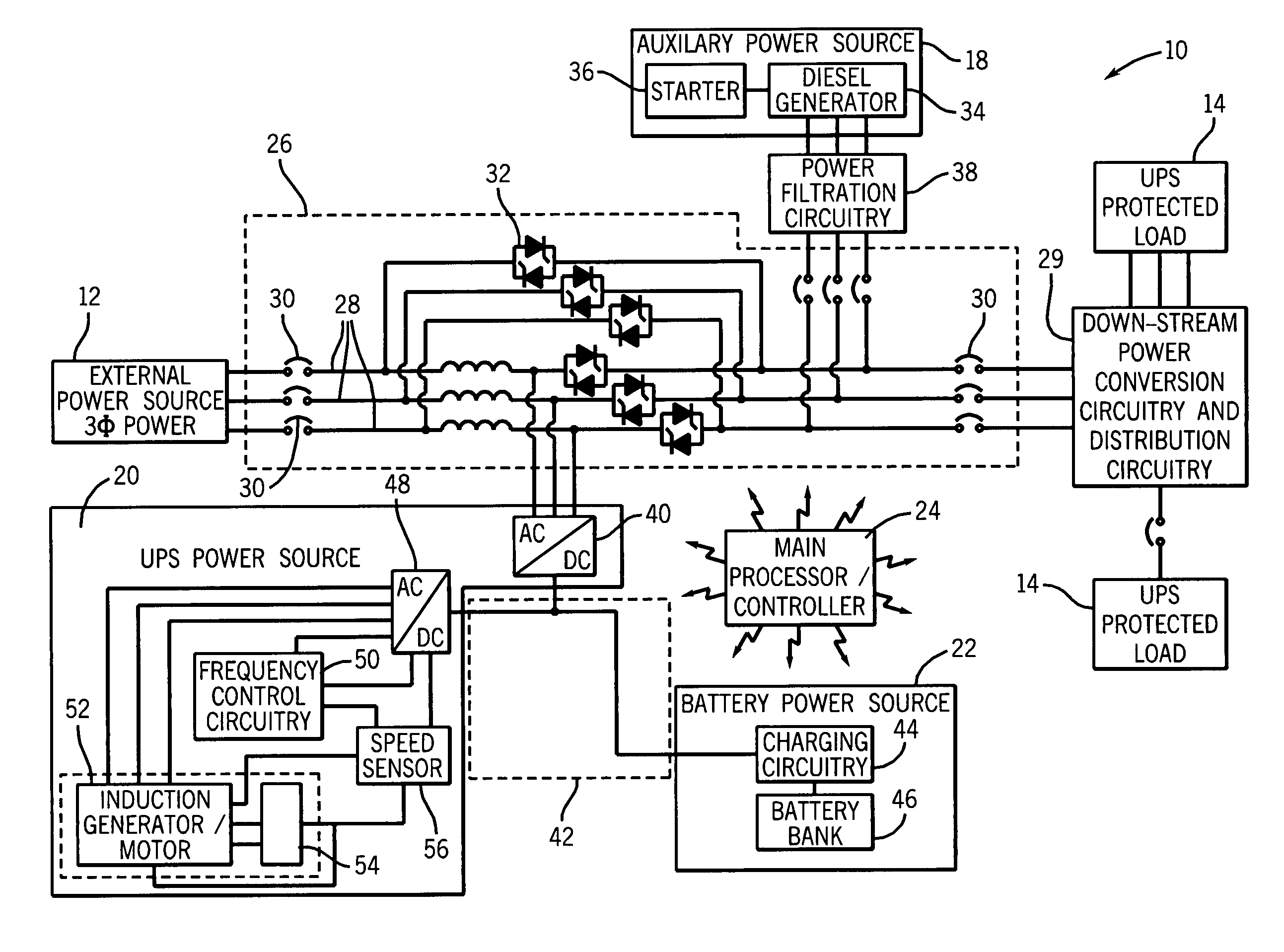
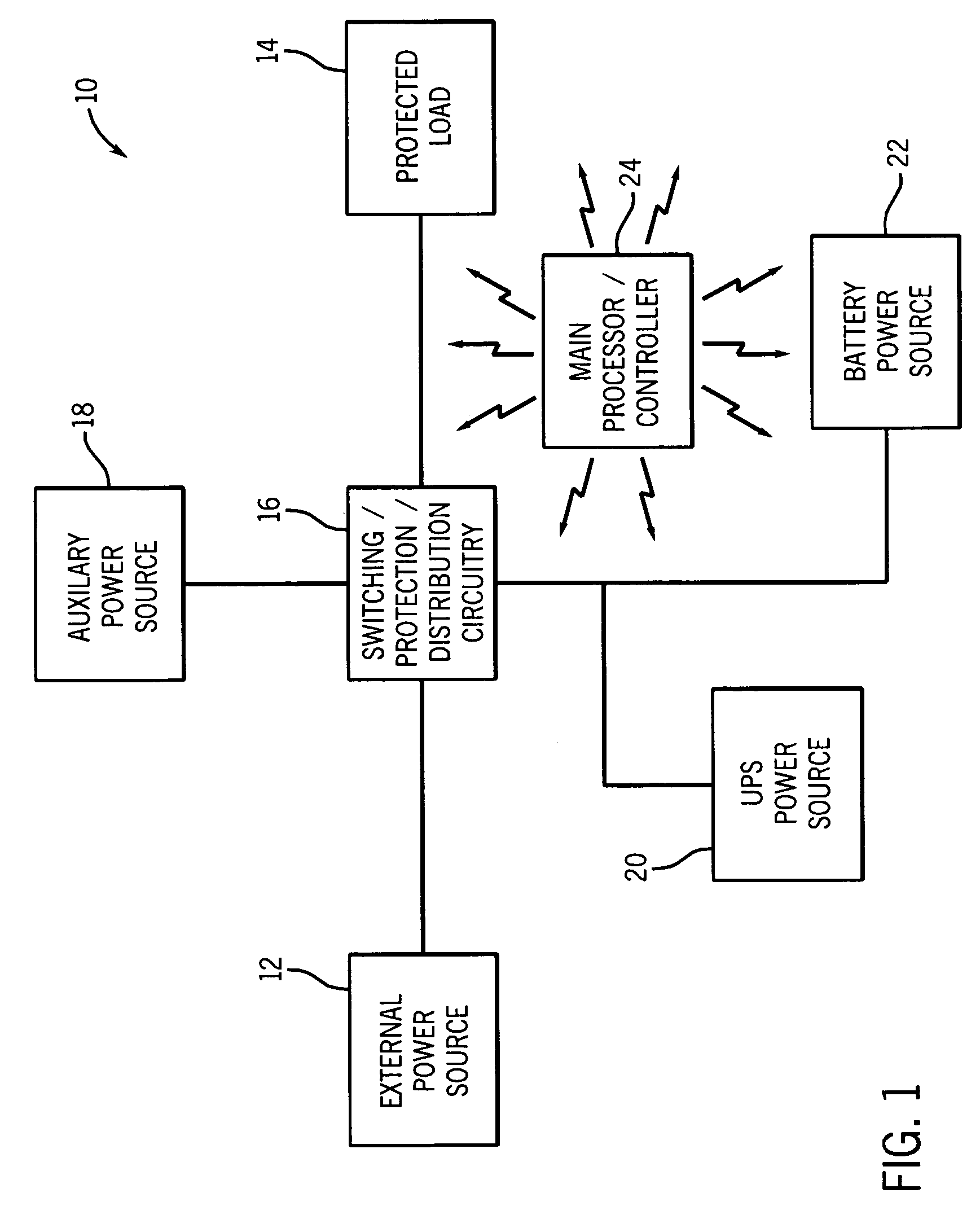
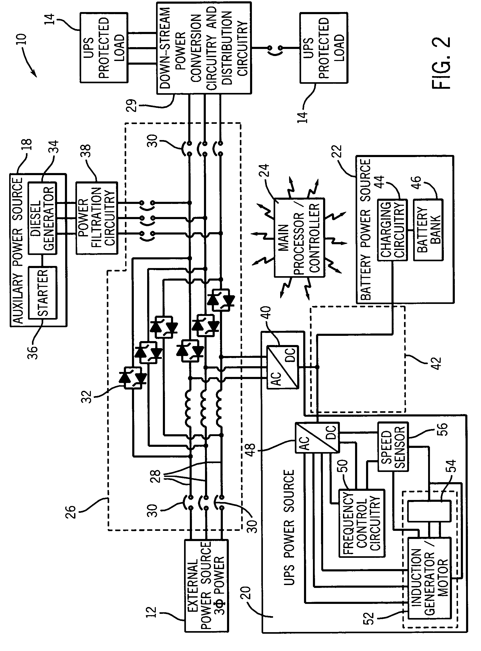
[0016]As discussed in detail below, the present invention provides methods and apparatus for providing power to loads. Although the following discussion focuses on providing transient power to a load, the present invention affords benefits to a number of power generation scenarios. Furthermore, the following discussion merely provides exemplary embodiments, and these examples are not intended to limit the scope of the appended claims. Additionally, as a preliminary matter, the definition of the term “or” for the purposes of the following discussion and the appended claims is intended to be an inclusive “or.” That is, the term “or” is not intended to differentiate between two mutually exclusive alternatives. Rather, the term “or” when employed as a conjunction between two elements is defined as including one element by itself, the other element itself, and combinations and permutations of the elements. For example, a discussion or recitation employing the terminology “‘A’ or ‘B’” inc...


PUM


Abstract

In accordance with certain exemplary embodiments, the present technique provides methods and apparatus for providing transient and uninterrupted power to protected loads. As one example, the present invention provides an induction device that operates as an induction motor to energize a kinetic energy storage device, such as a flywheel, during conventional operating conditions. However, in the event of a loss of primary power, the induction device, which is fed ac power at variable frequencies, begins to operate as an induction generator. For example, by varying the frequency of the input ac power such that the synchronous speed of the motor is exceeded by the rotating flywheel, the induction device acts as an induction generator and provides a transient operating power to the downstream loads until an auxiliary power source, such as a diesel generator, is brought on line.

Description

BACKGROUND[0001]The present invention relates generally to a transient power supply and, more particularly, to method and apparatus for providing transient power by converting stored kinetic energy into electrical energy.[0002]Typically, electrical devices receive operating power from an external power distribution grid that is coupled to a power generation facility, such as a power plant, for example. From time to time, this external power source can be interrupted, because of a malfunction in the generation facility and / or in the distribution grid, for instance. Accordingly, certain electrical devices are connected to an auxiliary power source, such as a diesel generator or a bank of batteries. Unfortunately, transitioning from the external power supply to the auxiliary power supply is generally not instantaneous and, as such, presents an interval of time during which the electrical devices are without power. For certain critical devices, such as computers or medical devices, even...

Claims


Application Information

Patent Timeline
Patent Type & Authority Patents(United States)
IPC IPC(8): F02D29/06
CPCH02J9/066H02K7/025Y02E60/16
Inventor POLLACK, JERRY J.MELFI, MICHAEL J.
Owner ROCKWELL AUTOMATION TECH
Learn More