Scale having a display and operating unit

a technology which is applied in the direction of measuring devices, instruments, weighing apparatuses, etc., can solve the problems of difficult attachment and easy removal of display and operating unit to and from the housing, and the limited work space available, so as to achieve the effect of simple engagement of the connection element into the coupling part and low construction

Active Publication Date: 2007-06-19
METTLER TOLEDO GMBH
View PDF12 Cites 12 Cited by
  • Summary
  • Abstract
  • Description
  • Claims
  • Application Information

AI Technical Summary

Benefits of technology

[0007]By a self-centering engaging coupling of the connection element on the bottom side of the scale housing, the display and operating unit can be attached rapidly and easily to the scale on the scale housing and removed therefrom without the use of any tools. For this purpose, a coupling part is positioned on the bottom of the scale housing, in which the connection element is able to engage in a self-centering way. If the display and operating unit is placed directly on the scale, the connection element is positioned below this unit in such a way that preferably no parts project. In addition, if the display and operating unit is positioned away from the scale, the connection element is removable, so that no parts project on the scale even in this situation. Furthermore, the scale, the display and operating unit and the connection element are easy to clean.
[0008]If the display and operating unit is placed directly on the scale, the scale may be lifted together with this unit in a stable way, since both parts are supported by the connection element. Therefore, the support base on which the scale stands can be cleaned without problems.
[0012]For a scale having a low construction, it is advantageous if the connection element is designed to be very flat and, in particular, is manufactured from an approximately 0.5 to 2 mm thick sheet of aluminium or sheet of steel or is manufactured as a plastic part.
[0013]In an advantageous refinement, each of the two support points comprise a wheel for the adjustment to level the scale, wherein the connection element is supported on the top of the particular wheel. In addition, the scale according to the present invention is designed in such a way that the display and operating unit and the scale stand on the support base independently from one another, so that the scale may be levelled independently from the display and operating unit.
[0014]The connection element is particularly formed in such a way that, in its installed state, it is oriented parallel to the support base of the scale approximately up to the area of the support points and then it is bent by an angle α in the direction of the coupling part, whereby a simple engagement of the connection element into the coupling part may be reached.

Problems solved by technology

In these locations, the available work space is frequently limited and therefore one of the requirements for such a scale is its flexibility with regard to its setup location and the positioning of the scale housing and the display and operating unit in relation to each other.
The attachability and easy removability of the display and operating unit to and from the housing is particularly difficult if the requirement exists of being able to place the display and operating unit both adjacent to the housing and also at a distance therefrom.

Method used


Image

  • Scale having a display and operating unit
  • Scale having a display and operating unit
  • Scale having a display and operating unit

Examples


Embodiment Construction

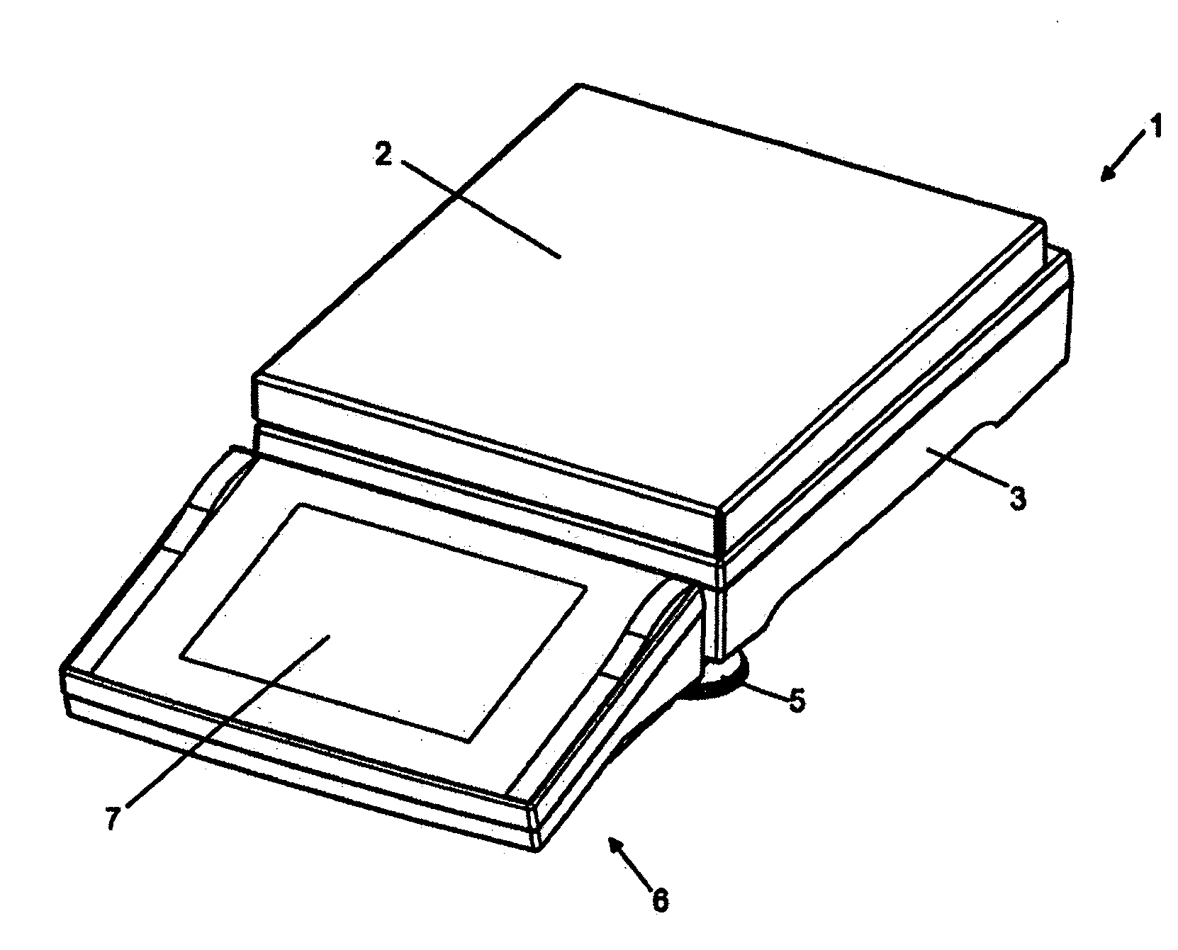
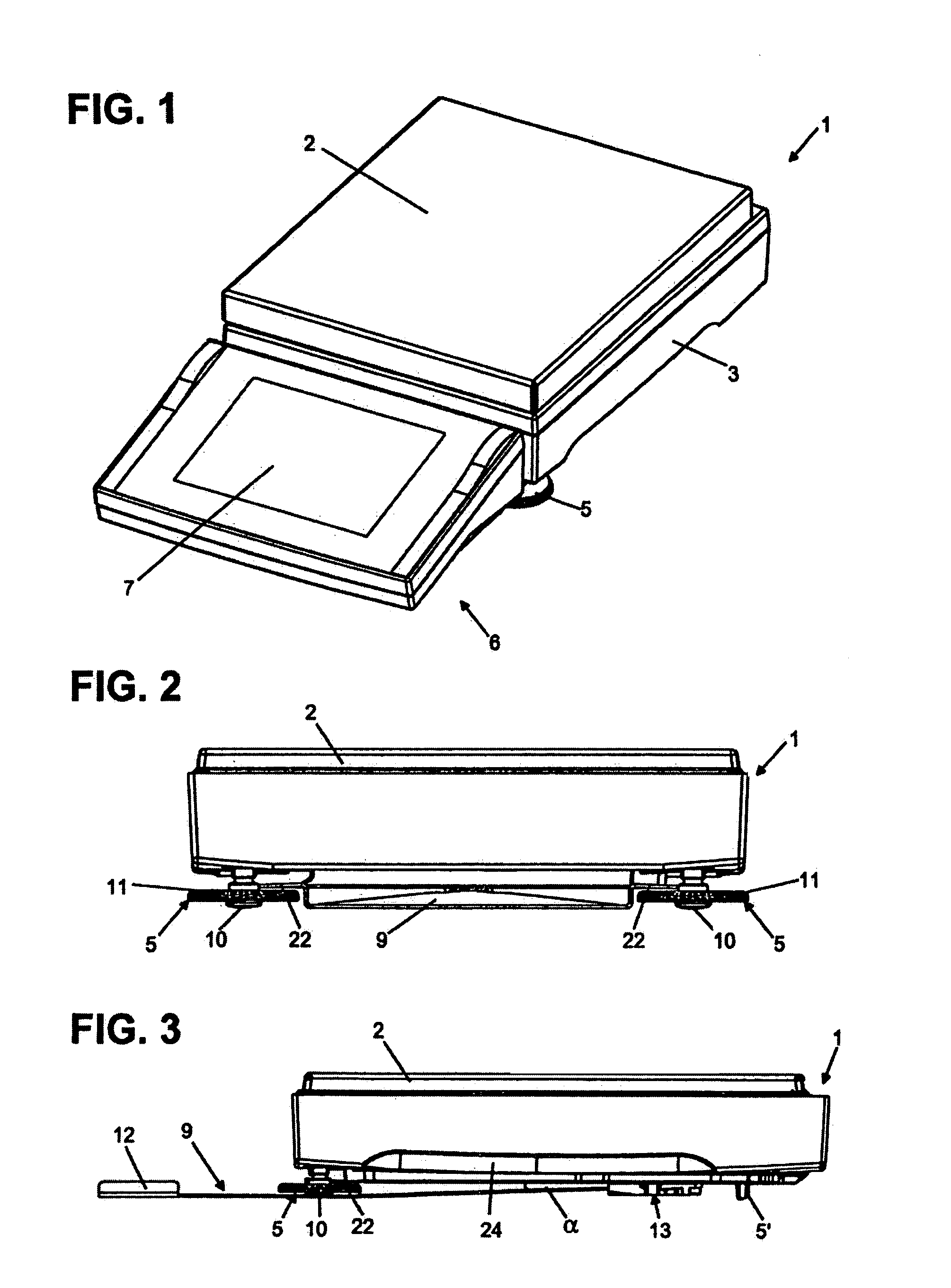
[0022]FIG. 1 shows a scale 1 as it may be placed in a laboratory, in a production area, or in a warehouse, for example. The scale 1 has a scale housing 3, in which the weighing cell and the weighing electronics (not shown here) are placed. The weighing pan 2 is connected to the weighing cell. In the example shown in the figure it extends over nearly the entire dimensions of the scale housing 3. The scale 1 stands on three feet or support points 5, respectively, of which only one is visible in the figure. A display and operating unit 6 is connected to the scale 1. It has a display screen 7 and buttons for operating the scale. This display and operating unit 6 can also be placed at a distance from the scale 1. According to the present invention, the display and operating unit 6 is removed from the scale 1 and / or attached to the scale 1 without the use of any tools. Therefore there is a connection element (see FIGS. 2 through 5), which provides a stable coupling of the display and oper...


PUM


Abstract

A scale (1) having a scale housing (3) serving to house the weighing mechanism and the weighing electronics, which stands on a support base on at least three support points (5,5′), is designed to be connectable to and disconnectable from a display and operating unit (6). A connection element (9) is provided to produce a mechanical coupling between the scale (1) and the display and operating unit (6), which can be attached to the bottom side of the scale housing (3) and is designed to be supported on at least two support points (5) of the scale (1) and can be engaged in a self-locating way in a third point on the bottom side of the scale housing (3).

Description

[0001]The present invention relates to a scale having a scale housing serving for housing the scale mechanism and the scale electronics, which stands on a support base on at least three support points, and having a display and operating unit, which is designed to be connectable to and disconnectable from the scale, a connection element being provided for producing a mechanical connection between the scale and the display and operating unit.BACKGROUND OF THE ART[0002]Such scales are preferably used in laboratories, at production sites, or in warehouses. In these locations, the available work space is frequently limited and therefore one of the requirements for such a scale is its flexibility with regard to its setup location and the positioning of the scale housing and the display and operating unit in relation to each other.[0003]Scales whose scale housing can be connected to their display and operating unit or can be positioned separately therefrom at the work space are known in th...

Claims


Application Information

Patent Timeline
Patent Type & Authority Patents(United States)
IPC IPC(8): G01G21/28
CPCG01G21/283
Inventor LEISINGER, ROGERMORF, PATRIK
Owner METTLER TOLEDO GMBH
Why Eureka
Try Eureka