Integral transverse flanges for a duct connecting system

a technology of transverse flanges and duct connections, which is applied in the direction of hose connections, lighting and heating apparatus, heating types, etc., can solve the problems of displaced corner connectors, and achieve the effects of increasing strength and rigidity across the joint, increasing strength and rigidity, and increasing rigidity

Inactive Publication Date: 2007-06-26
MET COIL SYSTEMS LLC
View PDF20 Cites 8 Cited by
  • Summary
  • Abstract
  • Description
  • Claims
  • Application Information

AI Technical Summary

Benefits of technology

[0019]It is another object of the present invention is to provide a transverse duct flange which provides increased strength and rigidity across the joint created by adjacent integral transverse duct flanges.
[0020]It is another object of the present invention is to provide a transverse duct flange which will allow for the use of the thinner gauge sheet metal in the construction of duct while providing the strength of a conventional duct flange using heavier gauge sheet metal.
[0021]It is another object of the present invention is to provide a transverse duct flange having additional strength which will alleviate the problems of bulging and leakage at adjacent duct flange joints.
[0022]A further object of the invention is to provide a transverse duct flange having additional strength which will alleviate the need to insert stiffeners or reinforcing bars, in certain applications, into the duct flange in order to strengthen the duct flange as is currently implemented with the prior art flanges.
[0023]A further object of the invention is to decrease the number of clips that are engaged about the respective connected adjacent flange portions to prevent leakage.

Problems solved by technology

It has been found, however, that the corner connectors will b displaced during manufacture and transport of the duct.

Method used


Image

  • Integral transverse flanges for a duct connecting system
  • Integral transverse flanges for a duct connecting system
  • Integral transverse flanges for a duct connecting system

Examples


Embodiment Construction

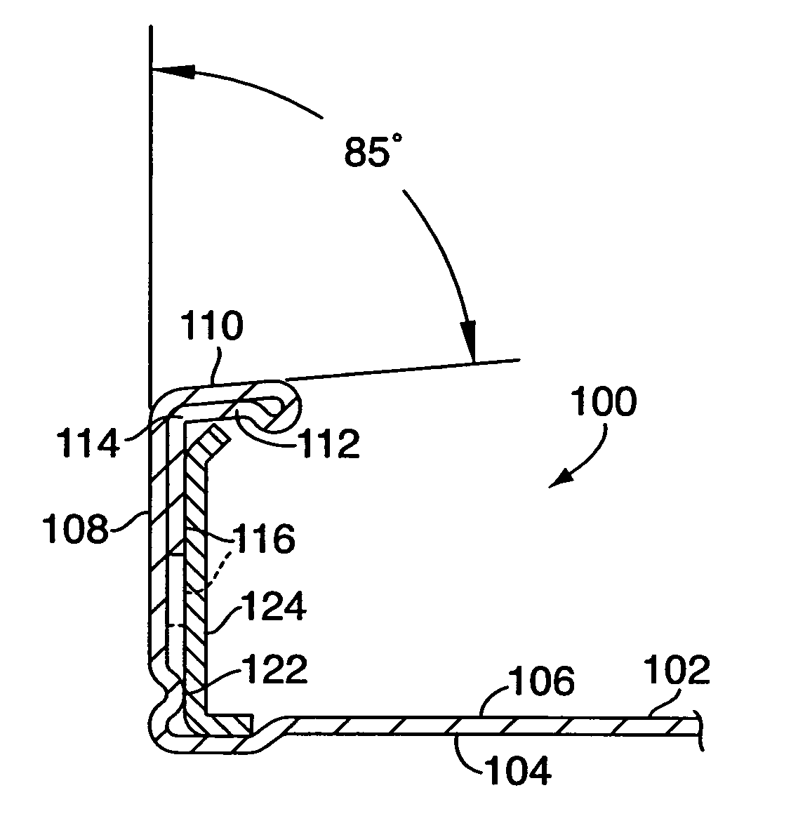
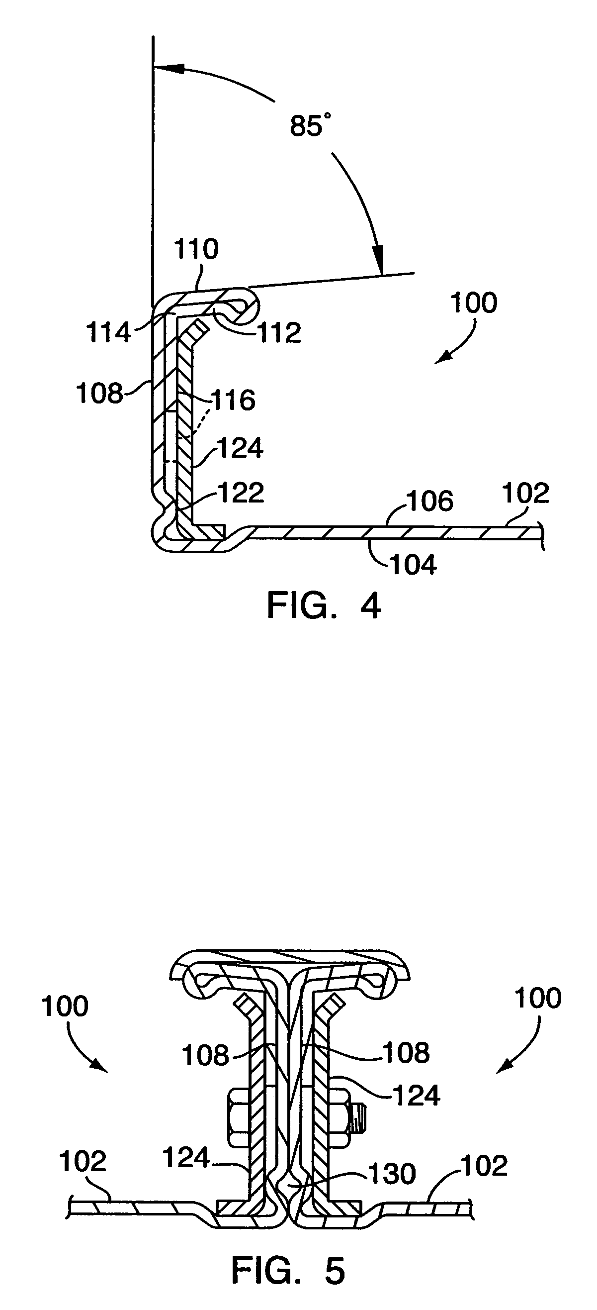
[0033]As shown in FIG. 4, the transverse flange 100 includes a duct wall 102 having an inside surface 104 and an outside surface 106. The flange 100 further includes a first upturned portion 108 which extends substantially perpendicularly from the duct wall 102, and a second rearwardly bent portion 110 extending substantially parallel to, and opposite of, the duct wall 102.

[0034]The end of second rearwardly bent portion 110 is turned over toward duct wall 90 and rounded back forming a third return portion 112. That is, as illustrated in FIG. 4, the second rearwardly bent portion 110 is turned approximately 180° towards the outside surface 106 of the duct wall 102. The return portion 112 is extended to form a fourth L-shaped portion 114 having a fifth portion 116 arranged to extend adjacent to and in close relation with the outside surface 106 of the first upturned portion 108.

[0035]One important aspect of the present invention is therefore that the third return portion 112 is bent b...


PUM


Abstract

An integral transverse flange for a duct includes a first upturned portion extending substantially perpendicularly from a duct wall of the duct. The flange further includes a second portion bent rearwardly from the first upturned portion, and a third return portion turned toward the duct wall and rounded back toward the first upturned portion from the second portion. A fourth L-shaped portion extends from the third return portion, the L-shaped portion having a first arm arranged adjacent to and in close relation with the second portion and a second arm arranged adjacent to and in close relation with the first upturned portion. A bead is formed in the first upturned portion.

Description

FIELD OF INVENTION[0001]The present invention relates, in general, to integral transverse flanges for a duct connecting system, and deals more particularly with integral transverse flanges having increased strength and sealing ability.BACKGROUND OF THE INVENTION[0002]Integral transverse flanges formed on the distal ends of rectangular ducts are well known in the art. These integral transverse flanges typically utilize angular corner connectors and related hardware to join with the opposing distal ends of matching rectangular ducts having similar integral transverse flanges.[0003]Owing to the vital role played by the integral transverse flanges, the structural integrity, strength and sealing ability of the flanges is of significant consideration.[0004]The prior art, particularly Heilman et al. (U.S. Pat. No. 4,466,641) and Fischer et al. (U.S. Pat. No. 4,579,375), the disclosures of which are incorporated herein by reference, disclose duct connecting systems using integral transverse...

Claims


Application Information

Patent Timeline
Patent Type & Authority Patents(United States)
IPC IPC(8): F16L35/00
CPCF16L23/14F24F13/0209
Inventor BORWIG, MICHAEL C.TOBEN, JOHN J.
Owner MET COIL SYSTEMS LLC
Why Eureka
Try Eureka