Bendable wrench

Active Publication Date: 2007-07-03
LEE YI MIN
View PDF8 Cites 48 Cited by
  • Summary
  • Abstract
  • Description
  • Claims
  • Application Information

AI Technical Summary

Benefits of technology

[0006]It is an objective of the present invention

Problems solved by technology

There are however problems with these conventional bendable wrenches.
Firstly, they include complicate structures made of many components.
It is troublesome to make and assemble these components.
Secondly, to change the angle between the head and the handle, a user has

Method used


Image

  • Bendable wrench
  • Bendable wrench
  • Bendable wrench

Examples


Example

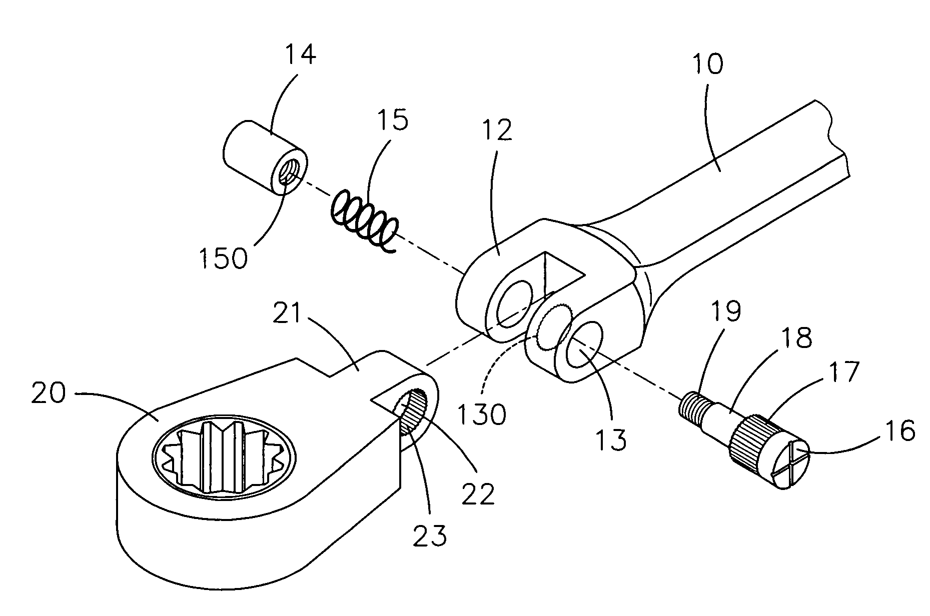
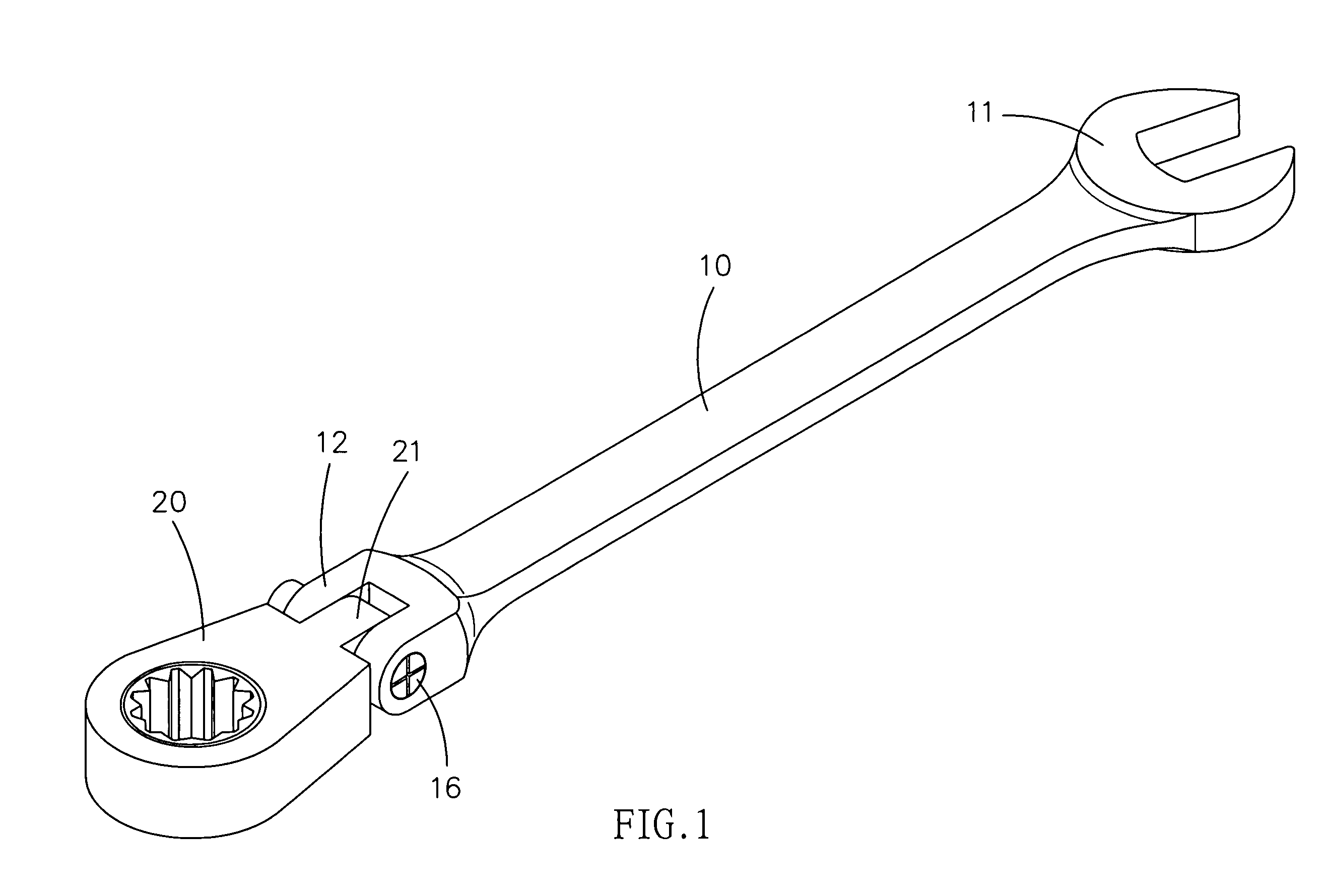
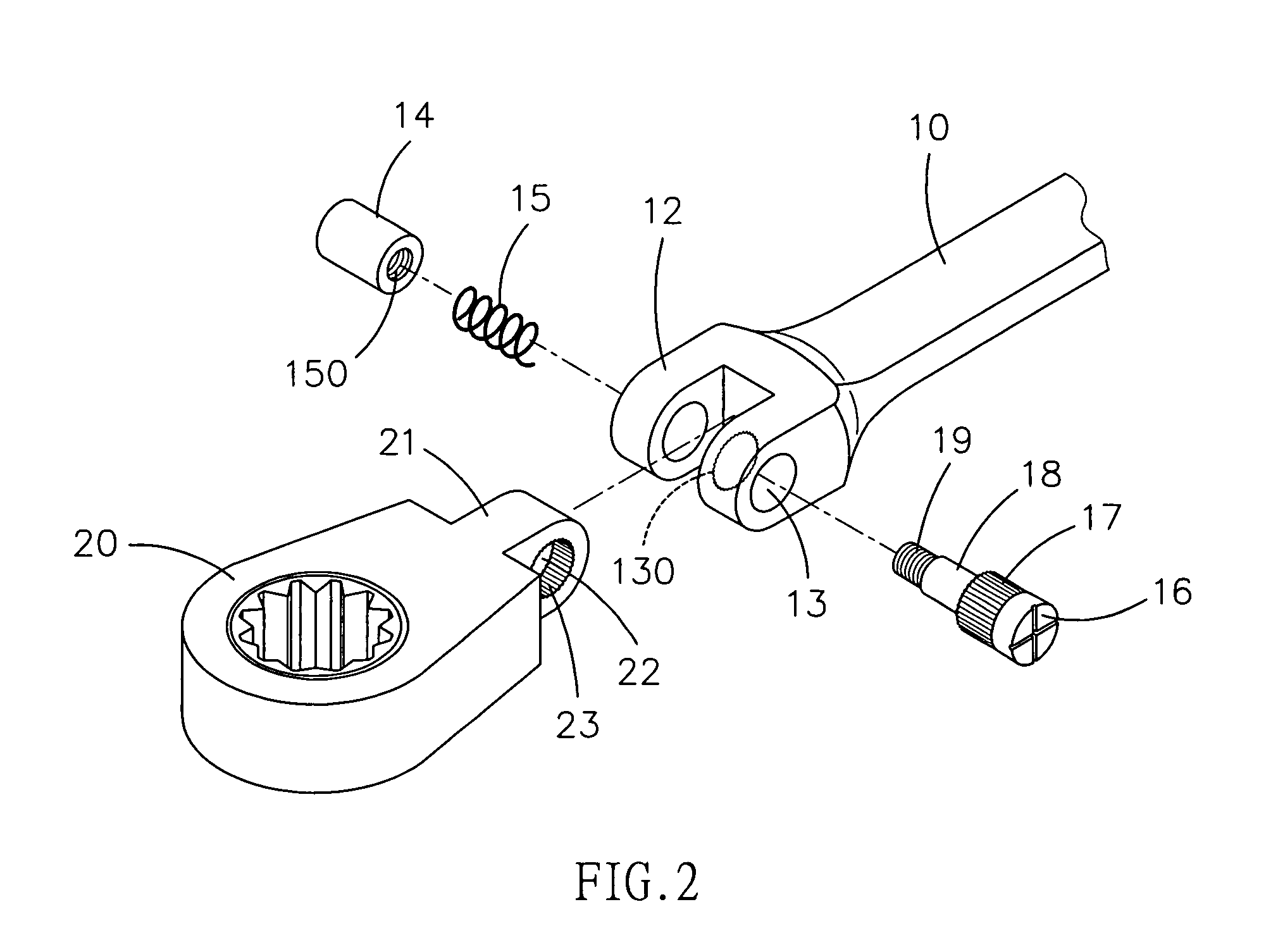
[0018]Referring to FIGS. 1 and 2, there is shown a bendable wrench in accordance with the preferred embodiment of the present invention. The bendable wrench includes a handle 10 formed with an open end 11 and a head 20 pivotally connected to the other end of the handle 10. The angle between the head 20 and the handle 10 can easily changed and firmly retained. The handle 10 may include a box end in another embodiment. The head 20 may be an open end, a box end, a money wrench head or a selective one-way wrench head.

[0019]The handle 10 includes two ears 12 formed at the end opposite to the open end 11. Each of the ears 12 defines an aperture 13. A plurality of teeth 130 is formed on the wall of the aperture 13 of one of the ears 12. The teeth 130 may extend only a portion of the axial length of the wall of the aperture 13 of the ear 12.

[0020]The head 20 includes an ear 21 formed at an end. The ear 21 defines an aperture 22. A plurality of teeth 23 is formed on the wall of the aperture ...


PUM


Abstract

A bendable wrench includes a handle, a head and a pivot. The handle includes a first ear formed thereon, a second ear formed thereon and a plurality of teeth formed on an internal side of the second ear. The head includes an ear and a plurality of teeth formed on an internal side of the ear thereof. The pivot is movably inserted in the ears so as to pivotally connect the head to the handle. The pivot includes a plurality of teeth that can be engaged with the teeth so as to firmly retain the angle between the head and the handle and disengage from the teeth of the head so that the angle between the head and the handle can be changed.

Description

BACKGROUND OF INVENTION[0001]1. Field of Invention[0002]The present invention relates to a bendable wrench and, more particularly, to a connecting device for connecting a head to a handle of a bendable wrench so that the angle between the head and the handle can be changed in a large range and firmly retained.[0003]2. Related Prior Art[0004]Wrenches are often used to tighten and slacken fasteners such as threaded bolts and nuts. Wrenches include one-way wrenches, socket wrenches, open-ended wrenches and box-ended wrenches. A wrench includes a handle and at least one head provided at an end of the handle. To fit in a limited and crooked working environment, there have been devised bendable wrenches such as disclosed in Taiwanese Patent Publication Nos. 450185 and 569860 and Taiwanese Patents I241940 and I242483. Such a bendable wrench includes a handle, a head and a connecting device for connecting to the head to the handle so that the angle between the head and the handle can be cha...

Claims


Application Information

Patent Timeline
IPC IPC(8): B25B23/16B25G1/00
CPCB25G1/063B25G3/38
Inventor LEE, YI MIN
Owner LEE YI MIN
Why Eureka
Try Eureka