Cabinet design of filter holder for pressurized espresso machines

a technology for espresso machines and filter holders, which is applied in beverage vessels, household appliances, kitchen equipment, etc., can solve the problems of cumbersome user, a lot of time spent trying to lock the mechanism or use the most existing pump espresso or steam espresso machines, and not very user-friendly

Active Publication Date: 2007-07-03
ELECTRICAL & ELECTRONICS LTD
View PDF25 Cites 33 Cited by
  • Summary
  • Abstract
  • Description
  • Claims
  • Application Information

AI Technical Summary

Problems solved by technology

The locking mechanisms employed or used by most existing pump espresso or steam espresso machines are not very user friendly.
It is very cumbersome for the user to locate and attach the filter holder unit into the locking mechanism on the brewing head unit of a coffee machine.
Frequently, the user spends a lot of time attempting to locate the locking position on the brewing head unit.
The drawback to the previous designs of mounting the boiler or the thermal block heating system on the brewing head unit is that the placement of the locking mechanism is limited by this design.
The limitations / drawbacks of the placing the heating system on top of the brewing head unit include:1. The weight of the heating system on the top will increase the force required to open the brewing head, which is not user friendly.2. When the heating system is fixed on top of the brewing head unit, it creates a constraint on the design of the locking mechanism.

Method used


Image

  • Cabinet design of filter holder for pressurized espresso machines
  • Cabinet design of filter holder for pressurized espresso machines
  • Cabinet design of filter holder for pressurized espresso machines

Examples


Embodiment Construction

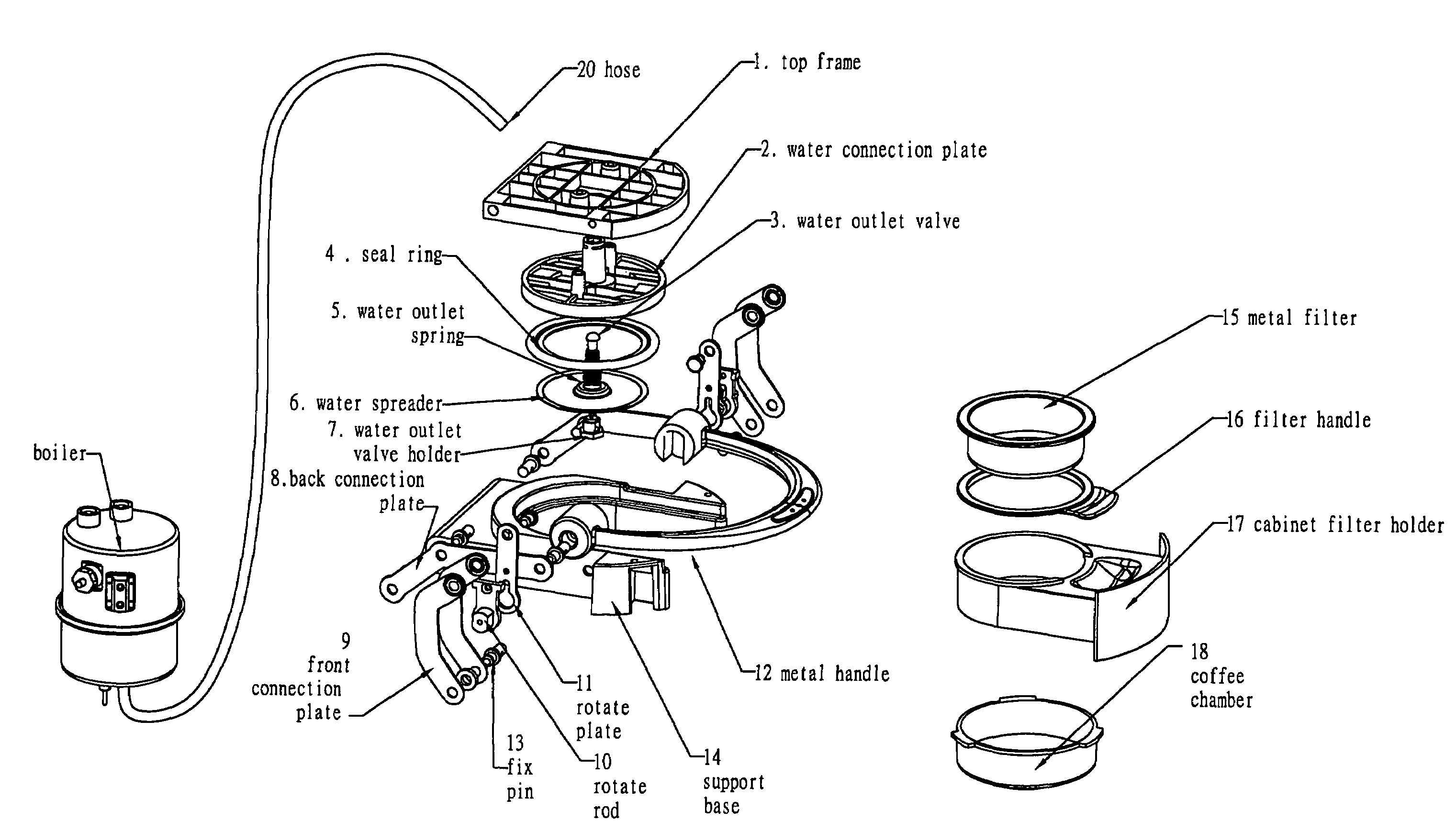
[0045]It is the object of this invention to provide a cabinet design of the filter holder. This invention provides a boiler / heating system which is separate from the brewing head unit of the coffee machine and a locking mechanism.

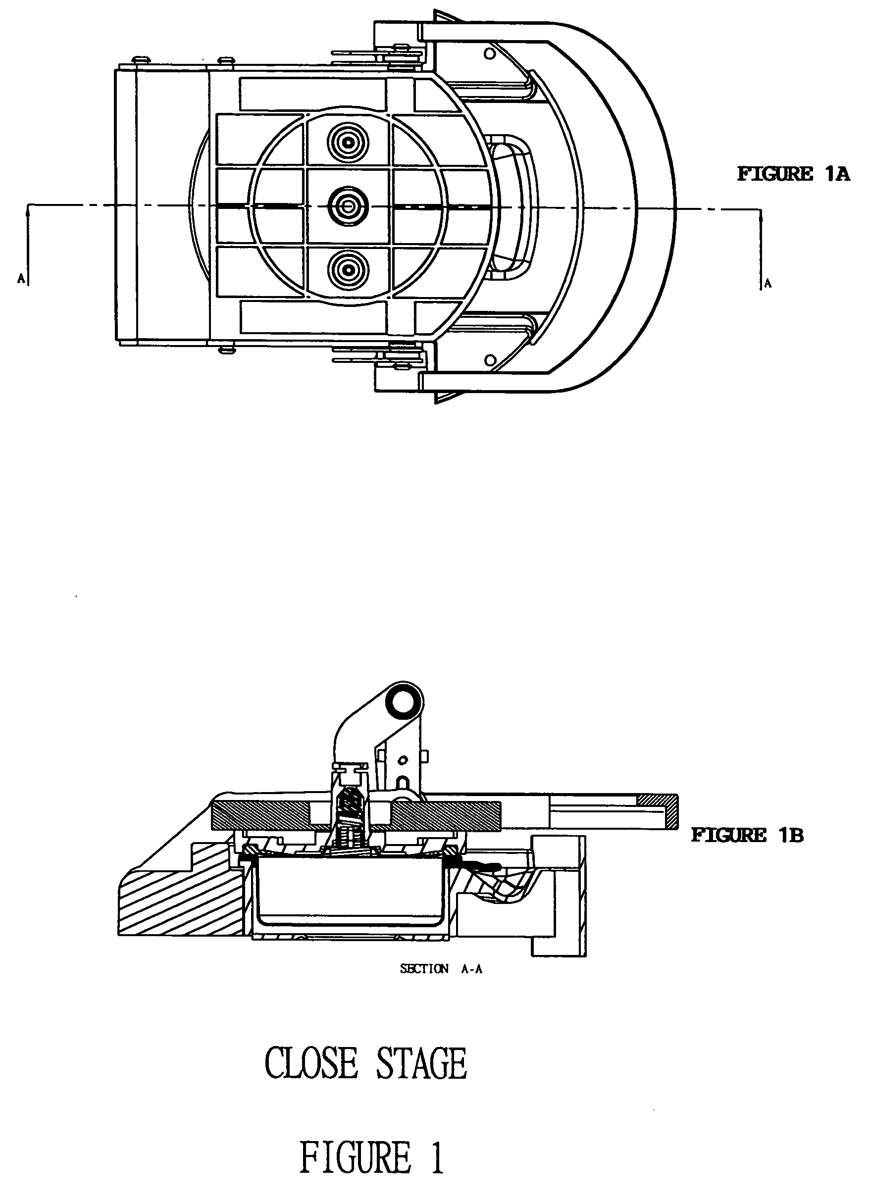
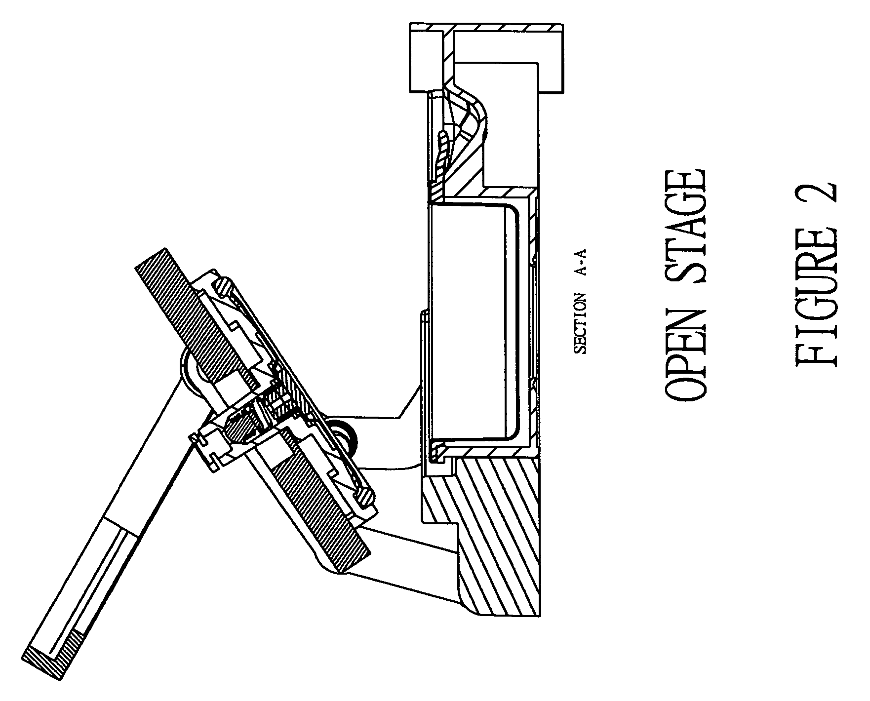
[0046]This invention provides a locking mechanism which is advantageous over prior art in that the filter holder unit does not need to be turned for it to lock. We only need slide in the filter holder and rotate down the handle. It is easier to operate and more efficient than the traditional turning lock mechanism.

Rotate to Lock Assembly of Construction I

[0047]This invention provides a brewing head assembly / unit (See FIGS. 1-5) of a coffee maker comprising: a rotate to lock assembly, a sealing assembly and a filter holder assembly / unit, operatively linked to sustain pressure of at least 5 bars. In an embodiment, the above-described rotate to lock assembly, sealing assembly, and filter holder assembly / unit are operatively linked and are capable of sustaining...


PUM


Abstract

This invention provides a brewing head unit of a coffee machine for inserting and locking the filter and the filter holder into the brewing head of a coffee machine. The filter and the filter holder can be inserted into the coffee machine visually. This invention further provides a simpler and easier method for inserting filter holder into a pressurized coffee machine. This invention also provides a cabinet filter holder which can be inserted or placed into the brewing head assembly / unit of a coffee machine by sliding the filter holder into the brewing head unit from front or side; by swinging the filter holder into the brewing head assembly / unit on a pivot; or by inserting the filter holder from the top. This invention further provides a brewing head assembly / unit wherein the locking mechanism is motor-driven. In one aspect of this invention, the method for opening and closing the brewing head assembly / unit of the coffee machine can be operated by remote control. This invention further provides a cabinet filter design wherein the boiler or heating system is separated from the brewing head assembly / unit.

Description

FIELD OF THE INVENTION[0001]The present invention relates to the design of a brewing head unit of a coffee machine comprising locking means for detachable attachment of a cabinet- or drawer-like filter holder to the brewing head unit of the coffee machine.BACKGROUND OF THE INVENTION[0002]Throughout this application, various references are referred to. Disclosures of these publications in their entireties are hereby incorporated by reference into this application to more fully describe the state of the art to which this invention pertains.[0003]The locking mechanisms employed or used by most existing pump espresso or steam espresso machines are not very user friendly. It is very cumbersome for the user to locate and attach the filter holder unit into the locking mechanism on the brewing head unit of a coffee machine. As a rule, the filter holder units which have so far been in common use for espresso machines have a brewing tray which is provided with a radially projecting handle and...

Claims


Application Information

Patent Timeline
Patent Type & Authority Patents(United States)
IPC IPC(8): A47J31/40A47J31/00A47J31/06A47J31/36A47J31/44
CPCA47J31/0626A47J31/0663A47J31/3685A47J31/4407A47J31/4467A47J31/0684A47J31/3666
Inventor CHEN, ANDREW YUEN CHINPOON, SUM FAT
Owner ELECTRICAL & ELECTRONICS LTD
Why Eureka
Try Eureka