Method of reducing a blocking artifact when coding moving picture

a technology of moving picture and block, applied in the field of moving picture block processing, can solve the problems of increasing the amount of bits to be transmitted, blocking artifacts that disturb the eyes of human beings, and serious problems, and achieve the effect of reducing the appearance of blocking artifacts

Inactive Publication Date: 2007-07-03
LG ELECTRONICS INC
View PDF5 Cites 35 Cited by
  • Summary
  • Abstract
  • Description
  • Claims
  • Application Information

AI Technical Summary

Benefits of technology

[0016]An object of the present invention is to provide a method for reducing a blocking artifact appearing when coding a moving picture that substantially obviates one or more of the limitations and disadvantages of the related art.

Problems solved by technology

However, the individual process causes blocking artifacts that disturb the eyes of human beings at boundaries between blocks.
However, this method of changing the processes of coding and decoding increases the amount of bits to be transmitted.
However, this method is applied to only a still picture because of an iteration structure and convergence time.
The blocking artifact is a serious problem in a low transmit rate moving picture compression.
Since a real-time operation is necessary in coding and decoding a moving picture, it is difficult to reduce the blocking artifact with a small operation capacity.
Consequently, the related art methods involve various problems and disadvantages when reducing a blocking artifact created in coding a moving picture.

Method used


Image

  • Method of reducing a blocking artifact when coding moving picture
  • Method of reducing a blocking artifact when coding moving picture
  • Method of reducing a blocking artifact when coding moving picture

Examples


Embodiment Construction

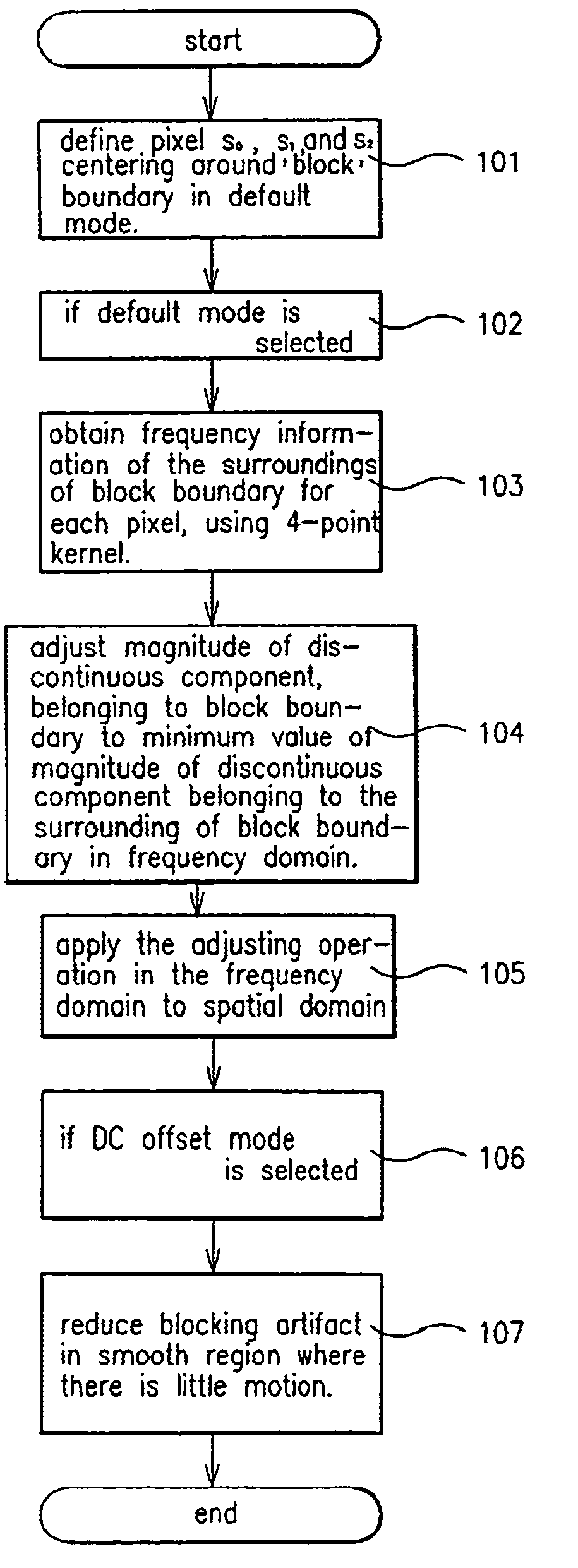
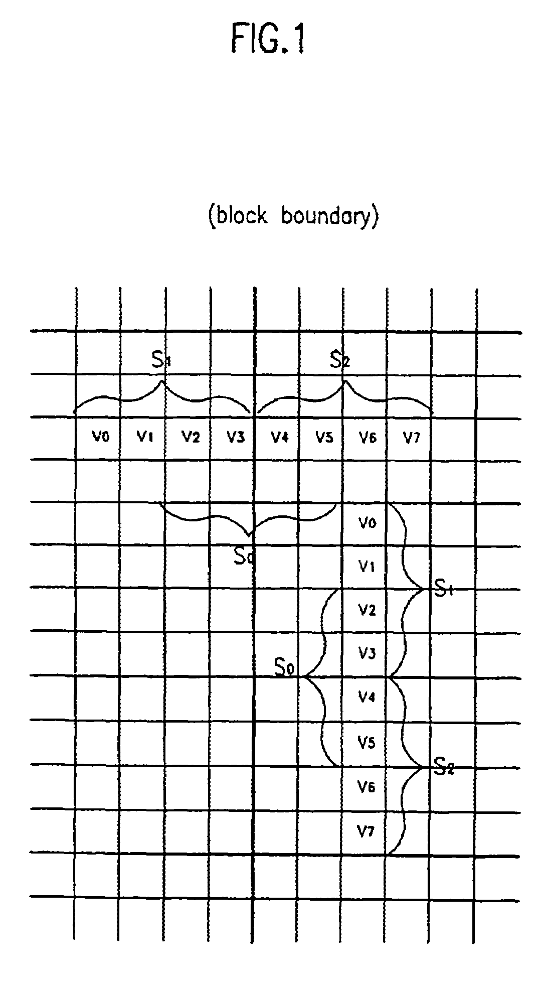
[0025]Reference will now be made to preferred embodiments of the present invention, examples of which are illustrated in the accompanying drawings. FIG. 1 illustrates typical horizontal and vertical block boundaries.

[0026]As shown in FIG. 1, in the dimensional image formed with respective four points of S0, S1, and S2 located around the block boundary, S1 and S2 are individually processed with a block-unit compression method. Thus, S1 and S2 are not influenced by the blocking artifact. However, S0 is located across a block boundary. Thus, S0 is directly influenced by the blocking artifact. The blocking artifact appears at the boundary between fixed block patterns in the form of a line of discontinuity.

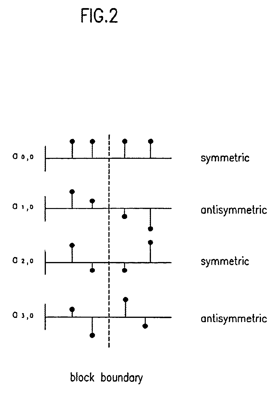
[0027]Preferred embodiments of the present invention use, for example, a frequency property to preserve complex regions at block boundaries. The frequency property around the boundary is preferably obtained by using a 4-point DCT kernel, which can be easily calculated. However, the pre...


PUM


Abstract

A method of coding a moving picture is provided that reduces blocking artifacts. The method can include defining a plurality of defining pixels S0, S1, and S2, which are centered around a block boundary. If a default mode is selected then frequency information of the surroundings of the block boundary is obtained. A magnitude of a discontinuous component in a frequency domain belonging to the block boundary is adjusted based on a magnitude of a corresponding discontinuous component selected from a pixel contained entirely within a block adjacent the block boundary. The frequency domain adjustment is then applied to a spatial domain. Or, a DC offset mode can be selected to reduce blocking artifacts in smooth regions where there is little motion.

Description

[0001]This application is a Continuation of application Ser. No. 09 / 010,446 filed Jan. 22, 1998 now U.S. Pat. No. 6,028,967.BACKGROUND OF THE INVENTION[0002]1. Field of the Invention[0003]The present invention relates to a moving picture process, and in particular to a method for processing blocks of a moving picture to increase a compression ratio and to improve coding efficiency.[0004]2. Background of the Related Art[0005]To efficiently compress a time variable video sequence, redundancy in the temporal domain as well as in the two dimensional spatial domain must be reduced. MPEG uses a discrete cosine transform (DCT) to reduce the redundancy in the two dimensional spatial domain and a motion compensation method to reduce the redundancy in the temporal domain.[0006]The DCT is a method of reducing the correlativity between data through a two dimensional spatial transformation. Each block in a picture is spatially transformed using the DCT after the picture is divided into blocks. D...

Claims


Application Information

Patent Timeline
Patent Type & Authority Patents(United States)
IPC IPC(8): G06T5/10
CPCH04N19/00H04N19/137H04N19/48H04N19/527H04N19/86H04N19/00909H04N19/00096H04N19/00145H04N19/00563H04N19/00593H04N19/126H04N19/176H04N19/182H04N19/198H04N19/80H04N19/85
Inventor KIM, HYUN MUNRA, JONG BEOMKIM, SUNG DEUKLEE, YOUNG SU
Owner LG ELECTRONICS INC
Why Eureka
Try Eureka